
Sterilization device for nail clippers

A sterilizing device and technology of nail clippers, applied in water supply devices, manicure or pedicure tools, applications, etc., can solve problems such as rising manufacturing costs of nail clippers, lower price competitiveness, complex design structures, etc., to improve hygiene Effects of cleanliness, easy placement and storage, and improvement of satisfaction

Pending Publication Date: 2021-12-03
THREE SEVEN CORP
View PDF8 Cites 0 Cited by
  • Summary
  • Abstract
  • Description
  • Claims
  • Application Information

AI Technical Summary

Problems solved by technology

[0011] Patent Document 1 discloses the following nail clippers, that is, provided with ultraviolet light emitting diodes, so that the nail clippers can be sterilized by ultraviolet light emitting diodes to manage fingernails or toenails hygienically, and a light source and a battery that generate ultraviolet rays for sterilization are combined with Nail clippers are installed integrally with a complex design structure, which is difficult to substantially manufacture and mass-produce. When manufacturing nail clippers, it will increase the manufacturing cost of nail clippers and reduce price competitiveness.
[0012] Patent Document 2 discloses a storage device for beauty tools that can store and store beauty tools such as nail clippers without consuming extra time, and can be cleaned, dried, and sterilized during storage and storage, which is easy Manage beauty tools and store them hygienically, but there is a problem that it is not suitable for sterilizing nail clippers after use and consumes too much management and maintenance costs

Method used


Image

  • Sterilization device for nail clippers
  • Sterilization device for nail clippers
  • Sterilization device for nail clippers

Examples


Embodiment Construction

[0046] Hereinafter, preferred embodiments of the present invention that can be easily carried out by those skilled in the art to which the present invention pertains will be described in detail with reference to the accompanying drawings. However, in explaining the structural principles related to the preferred embodiments of the present invention, when it is judged that specific descriptions related to known functions or structures unnecessarily obscure the gist of the present invention, the detailed descriptions will be omitted.

[0047] Also, throughout the specification, the same reference numerals are used for parts that have similar functions and perform similar functions.

[0048] And, throughout the specification, when it is mentioned that one part is “connected” to another part, it includes not only the case of “direct connection” but also the case of “indirect connection” via other elements therebetween. Moreover, when it is mentioned to "include" a certain structura...


PUM


Abstract

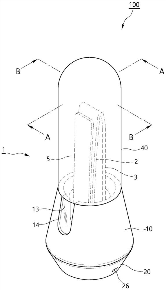
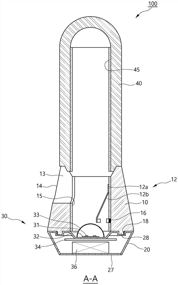
The invention provides a sterilization device for nail clippers. The present invention provides a sterilization device for nail clippers, comprising: an upper plate body and a lower plate body each having a cutting edge formed at the front end thereof; a supporting shaft, wherein the lower end of the supporting shaft is connected with the lower plate body; and a pressing member, the front end of which is rotatably assembled to the upper end of the supporting shaft penetrating through the upper plate body, the device comprising: a first body having an inner hole formed therethrough, a part of the body of the nail clippers being inserted into the inner hole so as to be vertically disposed, the nail clippers comprising the cutting edges of the upper plate body and the lower plate body; a second body which is detachably assembled at the lower end of the first body or integrally formed with the lower end of the first body, and in which at least one battery is provided; and a sterilization unit which is provided with at least one light source electrically connected to the battery on the upper surface of the second body corresponding to the cutting edges, and which irradiates ultraviolet rays for sterilization generated when the power source is applied to the nail clipper side.

Description

technical field [0001] The present invention relates to a sterilizing device for nail clippers, and more specifically, to a sterilizing device for nail clippers that can use ultraviolet light to sterilize nail clippers that remain in the user's hands during the process of temporarily placing and storing the used nail clippers. Bacteria or foreign matter on the surface of the nail clipper or the cutting edge are sterilized. Background technique [0002] Generally, nail clippers, which include curvilinear blades, are tools for cutting a person's fingernails and toenails to an appropriate length, and are one of the indispensable necessities among the hygiene tools of modern people. [0003] Human fingernails or toenails will continue to grow. Usually, fingernails grow at a rate of about 3mm per month, and toenails grow at a rate of about 1mm per month. Fingernails or toenails that grow longer than the specified length are inconvenient for daily use. Life, unhygienic in appeara...

Claims


Application Information

Patent Timeline
IPC IPC(8): A61L2/10A61L2/26
CPCA61L2/10A61L2/26A61L2202/11A45D29/02A61L2202/121A61L2202/122A61L2202/14
Inventor 金相默
Owner THREE SEVEN CORP
Learn More