Mechanical arm visual control method and device

A technology of a control device and a robotic arm, which is applied in the field of robotic arms, can solve the problems of inability to stably adsorb materials, cluttered and inclined materials, and affecting work efficiency.

Active Publication Date: 2021-12-03
QUZHOU COLLEGE OF TECH
View PDF13 Cites 2 Cited by
  • Summary
  • Abstract
  • Description
  • Claims
  • Application Information

AI Technical Summary

Problems solved by technology

[0003] In the prior art, for example, the mechanical arm disclosed in Patent Publication No. CN211920128U can move the parts to be grasped through the setting of the sweeping device so that it meets the identification signal of the visual sensor, so as to perform adsorption and grasping; It is necessary to grab different materials

Method used


Image

  • Mechanical arm visual control method and device
  • Mechanical arm visual control method and device
  • Mechanical arm visual control method and device

Examples


Embodiment 1

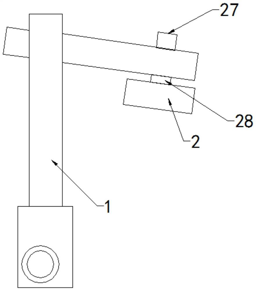
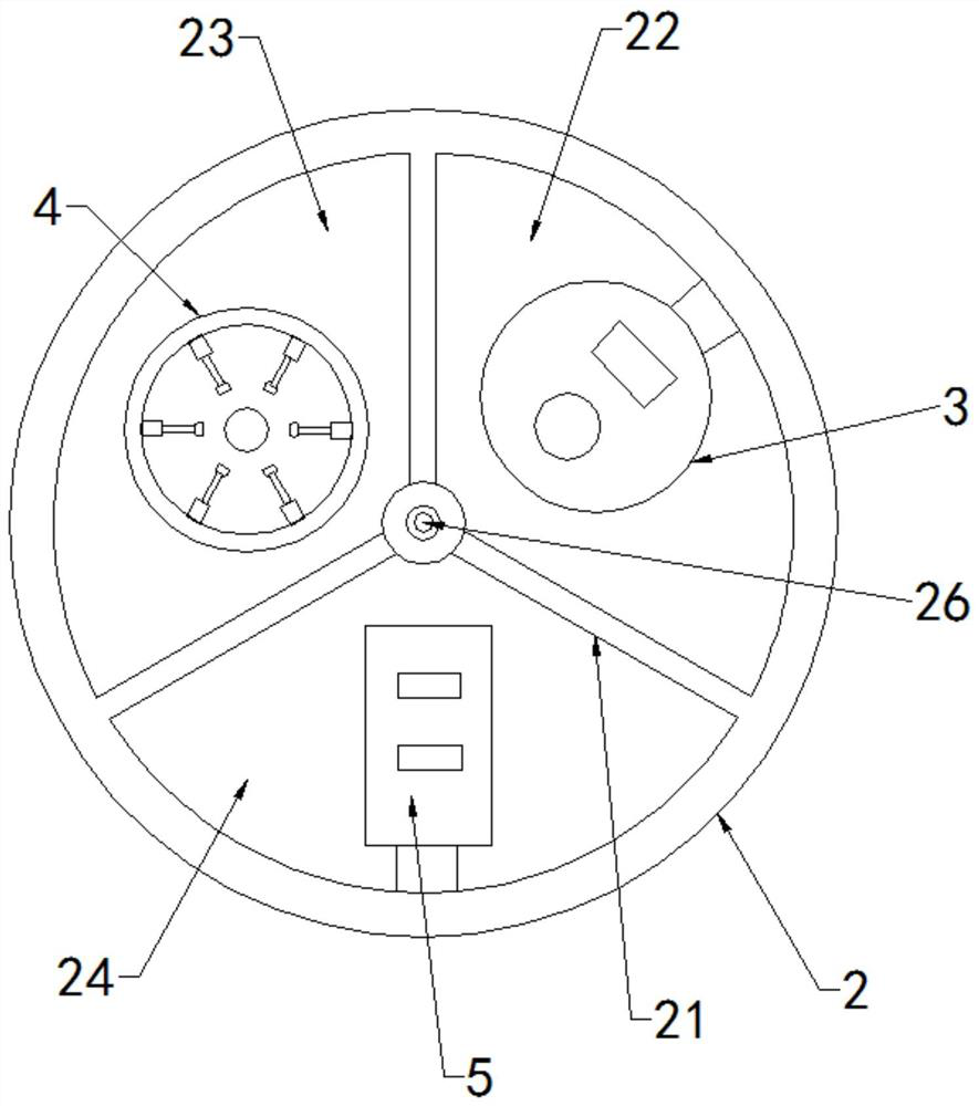
[0039] Such as Figure 1 to Figure 7 As shown, the present invention discloses a visual control device for a robotic arm. In a specific embodiment of the present invention, it includes a robotic arm main body 1 that can be rotated and adjusted. The bottom end of the robotic arm main body 1 It can be equipped with a signal output interface, and the signal output interface can be connected with the main control computer and external power supply of the mechanical arm through wires; the end of the main body 1 of the mechanical arm is equipped with an installation tube 2 with an installation cavity; In the installation cylinder 2 and separate the installation cavity of the installation cylinder 2 to form a first cavity 22, a second cavity 23 and a third cavity 24, the first cavity 22, the second cavity 23 and the third cavity The bodies 24 are all set into fan-shaped cavities; the mounting base 25 is located at the center of the bottom of the mounting cylinder 2 and is located at ...

Embodiment 2

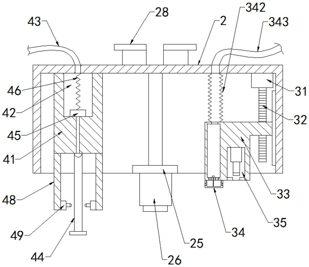
[0052] Such as Figure 6As shown, the difference between this embodiment and Embodiment 1 is that: in this embodiment, a toggle groove 35 is provided at the bottom of the first lifting seat 33, and a second dial is arranged in the toggle groove 35. The second toggle unit includes a first electric push rod 36, which is installed in the toggle groove 35; a toggle block 37, which is installed on the bottom output end of the first electric push rod 36, is received by the first electric push rod. The rod 36 controls the up and down movement; the limit ring 38 is arranged on the notch of the toggle groove 35, and the inner diameter of the annular structure matches the diameter of the toggle block 37; the toggle block 37 is set as an adsorption iron core, The toggle block 37 is externally connected with an electromagnetic control device for controlling the magnetic on-off of the adsorption iron core.

[0053] Through the above technical solution, when it is difficult to move parts t...

Embodiment 3

[0055] The invention also discloses a method for visual control of a robotic arm. In a specific embodiment of the invention, the method includes the following steps:

[0056] S1 Installation before use: Install the robotic arm on the workbench, adjust the position and angle of the robotic arm so that the visual sensor is aligned with the placement position of the part; debug based on the main control computer of the robotic arm to ensure that the visual sensor can collect the image of the part Send it to the vision processor to ensure that the target can be recognized and classified, calculate the two-dimensional coordinate position of the part target, debug the vertical height of the captured part, and complete the debugging to prepare for the grasping work;

[0057] S2 Adsorption and grabbing: After the first grabbing mechanism is aligned with the parts, the suction device is used to suck air through the suction pipe, and the gas in the suction chamber is sucked to form a neg...


PUM


Abstract

The invention discloses a mechanical arm visual control device. According to the technical scheme, the mechanical arm visual control device is characterized by comprising a mechanical arm body, partition plates, a mounting base, a shifting mechanism, a first grabbing mechanism and a second grabbing mechanism, and a mounting cylinder with a mounting cavity is assembled at the tail end of the mechanical arm body; the partition plates are arranged in the mounting cylinder and divides the mounting cavity of the mounting cylinder into a first cavity body, a second cavity body and a third cavity body, and the first cavity body, the second cavity body and the third cavity body are all arranged to be fan-shaped cavity bodies; the mounting base is arranged in the center of the bottom of the mounting cylinder and located at the joints of the partition plates, a visual processing unit is mounted on the mounting base, and the visual processing unit comprises a visual sensor, a visual processor and a distance measuring sensor; the shifting mechanism is arranged in the first cavity and used for shifting parts into the grabbing range of the mechanical arm; the first grabbing mechanism is arranged in the second cavity and used for adsorbing and grabbing the parts; and the second grabbing mechanism is arranged in the third cavity and used for clamping and grabbing the part. The mechanical arm visual control device has the beneficial effects of being stable in grabbing and high in working effect.

Description

technical field [0001] The invention relates to the technical field of manipulators, in particular to a method and device for visual control of a manipulator. Background technique [0002] Robotic arm is the Chinese translation of the word "ROBOT". According to national standards, an industrial robotic arm is defined as "its manipulator is automatically controlled, reprogrammable, multi-purpose, and can program more than 3 axes. It can be fixed or mobile. Used in industrial automation applications ". The manipulator is also defined as "a machine whose mechanism is usually composed of a series of mutually hinged or relatively sliding components. It usually has several degrees of freedom for grasping or moving objects (tools or workpieces)". Therefore, the industrial robotic arm may be understood as: a mechatronic device that anthropomorphizes the functions of the arm, wrist and hand; it can move any object or tool according to the time-varying requirements of the spatial po...

Claims


Application Information

Patent Timeline
IPC IPC(8): B25J15/00B25J15/02B25J15/06B25J13/08B25J19/00
CPCB25J15/0052B25J15/0253B25J15/0633B25J13/08B25J19/00
Inventor 周明安徐峰徐建亮
Owner QUZHOU COLLEGE OF TECH
Why Eureka
Try Eureka