Automatic steel bar binding system

A steel bar, automatic technology, applied in the field of steel bar automatic binding system, can solve the problems of reduced work efficiency and lack of adjustability, and achieve the effects of improving work efficiency, reducing labor intensity, and being convenient and quick to use.

Active Publication Date: 2021-12-03
北京好运达智创科技有限公司
View PDF7 Cites 2 Cited by
  • Summary
  • Abstract
  • Description
  • Claims
  • Application Information

AI Technical Summary

Problems solved by technology

[0002] In the box girder manufacturing process, the positioning mesh needs to be bound into a whole before pouring, and then put into the mold. The current positioning mesh binding is mostly single-bundle conveying and bundling. When transporting and binding, it is necessary to reasonably control the output of the steel bar conveyor, which reduces the work efficiency and lacks adjustability. It is necessary to actively adjust the position of the binding gun

Method used


Image

  • Automatic steel bar binding system
  • Automatic steel bar binding system
  • Automatic steel bar binding system

Examples


Embodiment 1

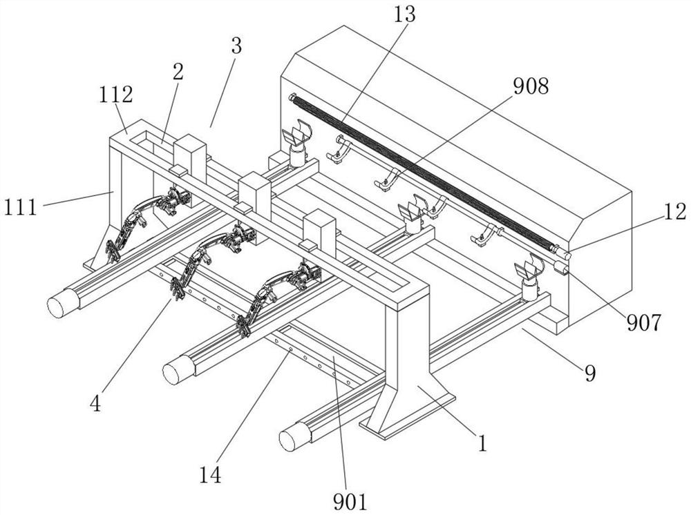
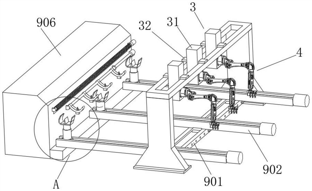
[0027] see figure 1 and Figure 6 , an automatic binding system for steel bars. The truss 1 is composed of two support bases 111 and a beam 112. The beam 112 is welded on the top of the two support bases 111. The first sliding platform 2 is set inside the beam 112. The second sliding platform 3 It is composed of a vertical plate 31 and a horizontal plate 32. The vertical plate 31 vertically passes through the gap between the two beams 112 and forms a sliding connection. The horizontal plate 32 is arranged on the top surface of the first slide table 2 and forms a sliding connection. connection, the two third sliding tables 6 are horizontally opposite to each other, and the third sliding table 6 is a ball screw sliding table. When in use, by sliding the second sliding table 3, the position of the mechanical arm 4 can be greatly adjusted. By setting The mechanical arm 4 can adjust the binding gun 8 at any position. The third sliding table 6 is a ball screw sliding table, and the...

Embodiment 2

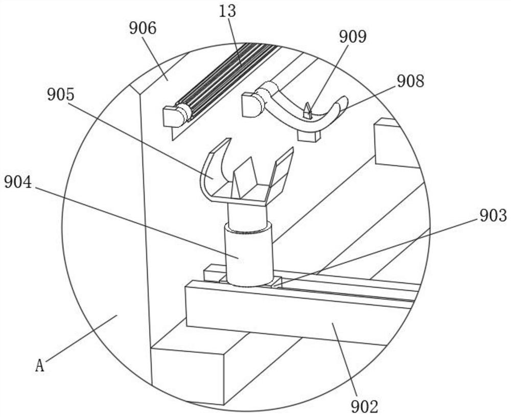
[0029] see Figure 1-6 , on the basis of Embodiment 1, the conveying mechanism 9 includes a first carriage 901 welded on the inside of the truss 1, the first carriage 901 is slidably connected with a conveying frame 902, and the inside of the conveying frame 902 is slidably connected with a moving frame through a ball screw. Block 903, the top of the moving block 903 is fixedly equipped with a hydraulic rod 904, the top of the hydraulic rod 904 is fixedly installed with a transport support frame 905, and one side of the transport frame 902 is movably connected with a steel bar conveyor 906, and one side of the steel bar conveyor 906 is fixed A first motor 907 is installed, and the output end of the first motor 907 is connected to a steel bar collection rack 908 through a transmission shaft. The inside of the steel bar collection rack 908 is provided with a separation electric push rod 909 for realizing the bundling of steel bars. The inside of the steel bar conveyor 906 A deli...


PUM


Abstract

The invention relates to the field of automatic steel bar binding, in particular to an automatic steel bar binding system. The automatic steel bar binding system comprises a truss, a first sliding table mounted at the top of the truss, three second sliding tables vertically mounted at the top of the first sliding table, mechanical arms mounted on mounting seats at the bottoms of the second sliding tables, and a conveying mechanism for conveying multiple bundles of steel bars, wherein the conveying mechanism comprises a first sliding frame welded to the inner side of the truss, and the first sliding frame is connected with a conveying frame in a sliding mode. According to the system, by arranging the conveying mechanism, multi-bundle conveying can be achieved, the conveying efficiency is improved, normal conveying of a reinforcing steel bar conveyor is not affected even when reinforcing steel bars with the small bundle number are conveyed and bundled, meanwhile, through cooperation of third sliding tables and binding guns, the distance between the binding guns can be automatically adjusted according to needs, different binding requirements are met, continuous operation can be achieved, use is convenient and fast, operation efficiency is greatly improved, and labor intensity is reduced.

Description

technical field [0001] The invention relates to the field of automatic binding of steel bars, in particular to an automatic binding system of steel bars. Background technique [0002] In the box girder manufacturing process, the positioning mesh needs to be bound into a whole before pouring, and then put into the mold. The current positioning mesh binding is mostly single-bundle conveying and bundling. To transport and bind, it is necessary to reasonably control the output of the steel bar conveyor, which reduces the work efficiency and lacks adjustability, so it is necessary to actively adjust the position of the binding gun. Contents of the invention [0003] The object of the present invention is to provide an automatic binding system for steel bars to solve the problems raised in the above-mentioned background technology. [0004] To achieve the above object, the present invention provides the following technical solutions: [0005] The steel bar automatic binding sy...

Claims


Application Information

Patent Timeline
Patent Type & Authority Applications(China)
IPC IPC(8): B28B23/00
CPCB28B23/00
Inventor 郑翼高阳郑彪
Owner 北京好运达智创科技有限公司
Why Eureka
Try Eureka