
Low-energy-consumption concrete mixing equipment

A technology for mixing equipment and concrete, which is applied in the field of low-energy concrete mixing equipment, can solve the problems of large energy consumption and energy loss, and achieve the effects of reducing energy consumption, reducing energy consumption rate, and reducing energy consumption

Pending Publication Date: 2021-12-03
董思槿
View PDF0 Cites 0 Cited by
  • Summary
  • Abstract
  • Description
  • Claims
  • Application Information

AI Technical Summary

Problems solved by technology

[0002] Concrete mixing equipment is a machine used to mix cement, sand and gravel aggregates and water and mix them into concrete mixtures. It mainly consists of mixing drums, feeding and unloading mechanisms, water supply systems, prime movers, transmission mechanisms, racks and According to the nature of the work, it is divided into batch type (batch type) and continuous type; according to the stirring principle, it is divided into self-falling type and forced type; according to the installation method, it is divided into fixed type and mobile type; according to the discharge method, it is divided into tipping type and Non-tilting type; according to the structure of the mixing drum, it can be divided into pear type, drum type, double cone type, disc vertical shaft type and circular groove horizontal shaft type, etc. The existing concrete mixing equipment consumes a lot of energy in the working process, and in the The energy loss during the movement is large, and a low-energy concrete mixing equipment is proposed to solve the above-mentioned problems

Method used


Image

  • Low-energy-consumption concrete mixing equipment
  • Low-energy-consumption concrete mixing equipment
  • Low-energy-consumption concrete mixing equipment

Examples


Embodiment Construction

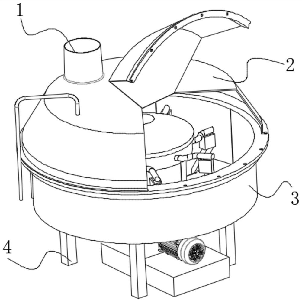
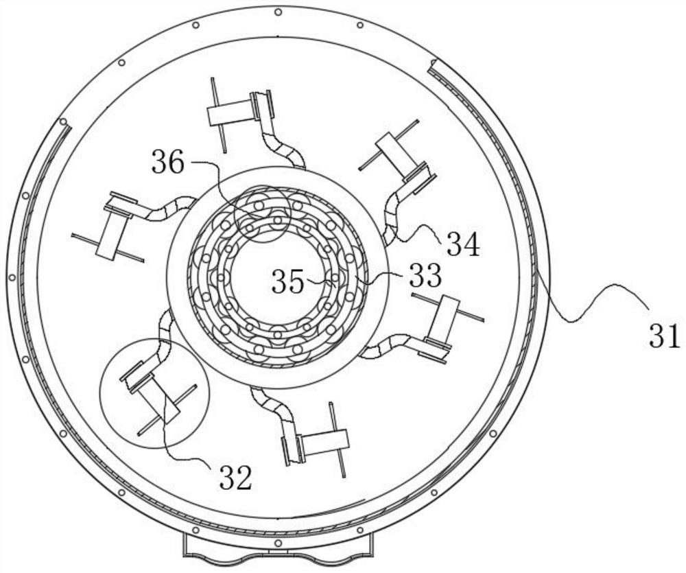
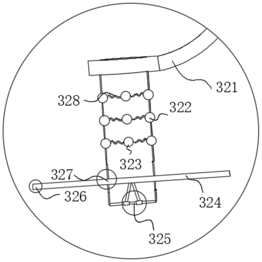
[0023] use Figure 1-Figure 7 A low energy consumption concrete mixing equipment according to an embodiment of the present invention is described as follows.

[0024] Such as Figure 1-Figure 7 As shown, a kind of low-energy concrete mixing equipment of the present invention comprises a leg 4; the top of the leg 4 is provided with a stirring tank 3, and the bottom of the top of the leg 4 is fixedly connected to the stirring tank 3, and the top of the stirring tank 3 is provided with a cover plate 2, and the top of the mixing tank 3 is fixedly connected to the bottom of the cover plate 2, the left end of the top of the cover plate 2 is provided with a feed port 1, and the top of the cover plate 2 is fixedly connected to the bottom of the feed port 1, and the legs 4 are set The purpose is to improve its stability.

[0025] Stirring tank 3 comprises tank wall 31, and the inside of tank wall 31 is uniformly provided with stirring rod 34, and the bottom of stirring rod 34 is prov...


PUM


Abstract

The invention belongs to the field of processing, and particularly relates to low-energy-consumption concrete mixing equipment which comprises supporting legs. A stirring tank is arranged on the tops of the supporting legs, the tops of the supporting legs are fixedly connected with the bottom of the stirring tank, a cover plate is arranged on the top of the stirring tank, the top of the stirring tank is fixedly connected with the bottom of the cover plate, a feeding hole is formed in the left end of the top of the cover plate, the top of the cover plate is fixedly connected with the bottom of the feeding hole, the stirring tank comprises a tank wall, stirring rods are uniformly arranged in the tank wall, a labor-saving mechanism is arranged at the bottom of each stirring rod, the bottoms of the stirring rods are fixedly connected with the tops of the labor-saving mechanisms respectively, a fixed ring is arranged in the pipe wall, acceleration mechanisms are uniformly arranged on the outer surface of the fixed ring, the outer surface of the fixed ring is movably connected with the inner walls of the acceleration mechanisms, a connecting ring is arranged at the outer ring position of the fixed ring, each labor-saving mechanism comprises a mounting rod, and mounting balls are symmetrically arranged at the bottom of each mounting rod.

Description

technical field [0001] The invention belongs to the field of processing, in particular to a low energy consumption concrete mixing equipment. Background technique [0002] Concrete mixing equipment is a machine used to mix cement, sand and gravel aggregates and water and mix them into concrete mixtures. It mainly consists of mixing drums, feeding and unloading mechanisms, water supply systems, prime movers, transmission mechanisms, racks and According to the nature of the work, it is divided into batch type (batch type) and continuous type; according to the stirring principle, it is divided into self-falling type and forced type; according to the installation method, it is divided into fixed type and mobile type; according to the discharge method, it is divided into tipping type and Non-tilting type; according to the structure of the mixing drum, it can be divided into pear type, drum type, double cone type, disc vertical shaft type and circular groove horizontal shaft type,...

Claims


Application Information

Patent Timeline
Patent Type & Authority Applications(China)
IPC IPC(8): B28C5/16B28C5/08
CPCB28C5/16B28C5/0831
Inventor 董思槿
Owner 董思槿
Learn More