
Packaging structure of mowing equipment with foldable charging station

A packaging structure and charging station technology, applied in packaging, packaging food, transportation and packaging, etc., can solve the problems of waste of container space, increase packaging cost, increase logistics cost, etc., achieve cost savings, reduce packaging volume, packaging structure less effect

Pending Publication Date: 2021-12-03
NANJING SUMEC INTELLIGENT TECH CO LTD
View PDF0 Cites 0 Cited by
  • Summary
  • Abstract
  • Description
  • Claims
  • Application Information

AI Technical Summary

Problems solved by technology

[0004] In order to better realize the auxiliary guiding and positioning function, the characteristic of the substrate is that the length and width are much larger than the thickness, and are larger than the vertical projection size of the mowing equipment. When packaging, the packaging size is often too large, resulting in a waste of space inside the container during transportation, increasing the cost. Packaging costs reduce the loading of containers and increase logistics costs
[0005] The base plate and the charging pile of the existing lawn mowing equipment are integrated. During transportation, the base plate and the charging pile are fixed and installed, resulting in a large packaging volume. At the same time, the charging pile is generally installed at the edge of the base plate. The center is located close to the side of the packaging box, which is less safe. During transportation, after the packaging box collides, it is easy to cause damage to the charging pile.

Method used


Image

  • Packaging structure of mowing equipment with foldable charging station
  • Packaging structure of mowing equipment with foldable charging station
  • Packaging structure of mowing equipment with foldable charging station

Examples


Embodiment 1

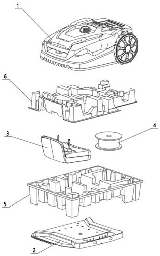
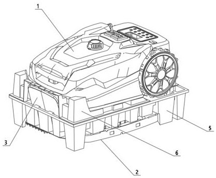
[0055] Such as figure 1 , 3 , 4, the packaging structure includes an upper packaging structure 6 and a lower packaging structure 5. The upper and lower packaging structures are two cover-like structures with opposite openings. The space for placing the charging pile 3, the coil 4 and other spare parts, the bottom of the lower packaging structure is provided with a space for placing the folded substrate, and the top of the upper packaging structure can be placed for mowing equipment 1.

[0056] Such as Figure 5 , 6 Shown is the upper packaging structure 6, the opening of the upper packaging structure 6 faces downward, and the top of the upper packaging structure 6 is provided with front wheel grooves 602 and rear wheel relief openings 603 corresponding to the front wheels, rear wheels, and mowing cutter heads on the mowing equipment. And the cutter head groove 601, the position of the rear wheel relief port 603 is also provided with a shaft groove 604, and the bottom of the...

Embodiment 2

[0062] The difference between Embodiment 2 and Embodiment 1 is that upper positioning parts 605 are provided at the four corners of the upper packaging structure 6, and the upper positioning parts 605 are protrusions that cover the shell of the mowing equipment, and at the same time, the upper positioning parts The outside shape of the outer part fits the outer packing box.

[0063] There is a certain distance between the upper positioning parts 605 at one end of the tail of the mowing equipment, which leaves the middle of the tail of the mowing equipment free for easy grasping. Usually, the gripping position of the mowing equipment is located at the bottom of the middle of the tail of the mowing equipment.

[0064] A substrate groove 504 is provided at the bottom of the lower packaging structure 5 for placing the folded substrate 2 . A lower positioning part 506 is arranged around the bottom of the lower packaging structure 5. The inner side of the lower positioning part 506 ...

Embodiment 3

[0068] As a further improvement of Embodiment 1 and Embodiment 2, after the charging pile 3 is placed in the charging pile placement slot 501, the end of the charging pile 3 is located at the end of the lower packaging structure 5 and protrudes from the opening end of the lower packaging structure 5. The position of the upper packaging structure 6 corresponds to the charging pile 3. There is a charging pile relief opening 606, which leaves space to prevent the charging pile from being squeezed. Forming a section structure similar to a wave or pulse shape, it has a certain degree of elasticity and support strength. During transportation, when the charging pile shakes and collides with the side wall of the packaging structure at the charging pile exit 606, it can be cushioned to improve protection.


PUM


Abstract

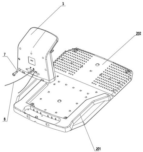
The invention discloses a packaging structure of mowing equipment with a foldable charging station. A charging pile of the foldable charging station is detachably connected with a base plate, the base plate comprises at least two base plate units, the charging pile is connected with one base plate unit, the base plate units are unfolded or folded in a movable connection mode, and the charging pile is connected with a power source and a boundary line coil; the packaging structure comprises a first packaging structure and a second packaging structure, and after the first packaging structure and the second packaging structure are in contact with each other, a space for placing the charging pile and the coil is formed inside; the bottom of a complete structure formed after the first packaging structure and the second packaging structure make contact with each other is provided with a space for containing the folded base plate; and the mowing equipment is placed on the top of the complete structure formed after the first packaging structure and the second packaging structure make contact with each other. According to the packaging structure of the mowing equipment with the foldable charging station, the packaging and logistics cost can be reduced.

Description

technical field [0001] The invention relates to the field of intelligent lawnmowers, in particular to a packaging structure for lawnmowers with a foldable charging station. Background technique [0002] As unattended lawn mowing equipment, due to its intelligence, it can help users save a lot of time for mowing grass, and it is becoming more and more popular in families with lawns. The work of mowing equipment relies on electric energy, but the capacity of the built-in battery is limited, and the mowing equipment still needs to return to the charging pile frequently for charging to supplement the electrical energy. [0003] As an essential part of mowing equipment, charging piles are generally packaged with the mowing equipment for delivery and transportation. The charging pile includes three parts: the substrate, the coil and the charging pile. The function of the substrate is to assist the mowing equipment to assist in guiding and positioning when returning to the chargi...

Claims


Application Information

Patent Timeline
Patent Type & Authority Applications(China)
IPC IPC(8): B65D25/10B65D25/02B65D81/133B65D85/68A01D34/00
CPCB65D25/10B65D25/02B65D81/133B65D85/68A01D34/00
Inventor 吴晓飞郝仲峰刘楷
Owner NANJING SUMEC INTELLIGENT TECH CO LTD
Learn More