Subminiature integrated synchronous jacking device

A technology of synchronous jacking and jacking devices, which is applied in the direction of fluid pressure actuation devices, fluid pressure actuation system components, servo motors, etc., and can solve problems such as complicated installation, heavy weight, and large operating errors of jacking hydraulic cylinders. Achieve the effect of simple circuit control, simple assembly form and large installation range

Pending Publication Date: 2021-12-03
美福特(徐州)数字工程有限公司
View PDF0 Cites 0 Cited by
  • Summary
  • Abstract
  • Description
  • Claims
  • Application Information

AI Technical Summary

Problems solved by technology

[0002] In the prior art, when bridges are being maintained, oil pipes are still used to connect and operate through a general hydraulic station, and the jacking devices are connected to each jacking device through the hydraulic station and the laying oil pipes. It is convenient and quick to install, and at the same time, the maximum number of channels controlled by the hydraulic station has great limitations in use, and cannot adapt to large-scale super multi-point synchronous jacking projects
The jacking devices connected to the operation of the hydraulic station are generally 8, 16 or 32. When installing and using, the number of jacking devices should not exceed the maximum number provided by the hydraulic station; The pipeline greatly prolongs the construction period of the installation equipment and requires skilled staff to pay a lot of high-intensity labor; at the same time, when the jacking device is synchronously controlled by the hydraulic station, the operation error of the jacking hydraulic cylinder in the jacking device is generally large, For components that require precise simultaneous jacking, such as bridge decks, there is a greater risk of damage

Method used


Image

  • Subminiature integrated synchronous jacking device
  • Subminiature integrated synchronous jacking device
  • Subminiature integrated synchronous jacking device

Examples


Embodiment Construction

[0022] The following will clearly and completely describe the technical solutions in the embodiments of the present invention with reference to the accompanying drawings in the embodiments of the present invention. Obviously, the described embodiments are only some, not all, embodiments of the present invention. Based on the embodiments of the present invention, all other embodiments obtained by persons of ordinary skill in the art without making creative efforts belong to the protection scope of the present invention.

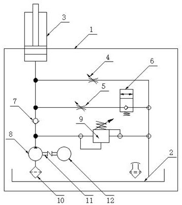
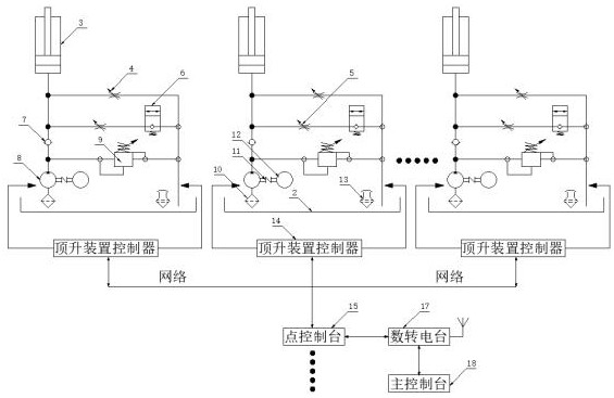
[0023] see Figure 1-3 , the present invention provides a technical solution: an ultra-small integrated synchronous jacking device, including a protective casing 1, the outer wall of the protective casing 1 is connected to or embedded with a fuel tank 2, and the fuel tank 2 and the protective casing 1 can be set as a split structure , can also be set as an integrated structure, then the oil cavity tube is set in the inner cavity of the protective casing 1 and ...


PUM


Abstract

The invention discloses a subminiature integrated synchronous jacking device in the technical field of jacking. The subminiature integrated synchronous jacking device comprises protection machine shells, the outer walls of the protection machine shells communicate with oil tanks or embedded oil tanks, and integrated jacking hydraulic oil cylinders are arranged in the protection machine shells. An emergency rotary knob, a speed regulating valve, a safety overflow valve, a one-way valve, a hydraulic pump, an electromagnetic reversing valve, an oil suction pump, a coupler, an oil pump and an oil return pump are sequentially arranged on each protection machine shell, each protection machine shell is electrically connected to a jacking device controller, the jacking device controllers are connected to ejecting devices with the same points through wired and wireless networks, the synchronous jacking control is performed, the installation is convenient, the time is saved, the assembly form is simpler, the circuit control is simpler, the miniaturized jacking device operates more stably, the maximum height error among the synchronous jacking devices is 0.05 millimeter, the height synchronous positioning can better protect larger and longer components, and the requirement for maintenance of a larger bridge floor is better met.

Description

technical field [0001] The invention relates to the technical field of jacking, in particular to an ultra-small integrated synchronous jacking device. Background technique [0002] In the prior art, when bridges are being maintained, oil pipes are still used to connect and operate through a general hydraulic station, and the jacking devices are connected to each jacking device through the hydraulic station and the laying oil pipes. It is convenient and quick to install. At the same time, the maximum number of channels controlled by the hydraulic station has great limitations in use, and it cannot adapt to large-scale super multi-point synchronous jacking projects. The jacking devices connected to the operation of the hydraulic station are generally 8, 16 or 32. When installing and using, the number of jacking devices should not exceed the maximum number provided by the hydraulic station; The pipeline greatly prolongs the construction period of the installation equipment and...

Claims


Application Information

Patent Timeline
Patent Type & Authority Applications(China)
IPC IPC(8): F15B11/22F15B21/08
CPCF15B11/22F15B21/08
Inventor 汪鲜
Owner 美福特(徐州)数字工程有限公司
Why Eureka
Try Eureka