
Near-field optical polarization spectrometer

A near-field optics and spectrometer technology, applied in polarization spectroscopy, scientific instruments, optical devices, etc., can solve the problems of only 5 microns, reduce the accuracy of measurement results, and limit the lateral resolution of the spot size. The effect of meeting the needs of accurate measurement

Pending Publication Date: 2021-12-03
INST OF MICROELECTRONICS CHINESE ACAD OF SCI
View PDF6 Cites 0 Cited by
  • Summary
  • Abstract
  • Description
  • Claims
  • Application Information

AI Technical Summary

Problems solved by technology

Although the longitudinal resolution of traditional polarimeters depends on the phase measurement sensitivity of the instrument, and generally can achieve Angstrom level, the lateral resolution of polarimeters is limited by the spot size, and the diameter of the spot size of micro-spot type polarimeters is between 25 and 50 μm. In the meantime, the spatial resolution of imaging-type polarimeters can only reach the order of 5 microns. Even if the detection wavelength develops to the deep ultraviolet band, the lateral resolution of traditional polarimetric spectrometers can at most be Realize ten times the diffraction limit, and it is difficult to achieve lateral spatial resolution below the micron level
For samples with fine structures, the averaged measurement will lead to large errors and reduce the accuracy of measurement results

Method used


Image

  • Near-field optical polarization spectrometer
  • Near-field optical polarization spectrometer
  • Near-field optical polarization spectrometer

Examples


no. 1 example

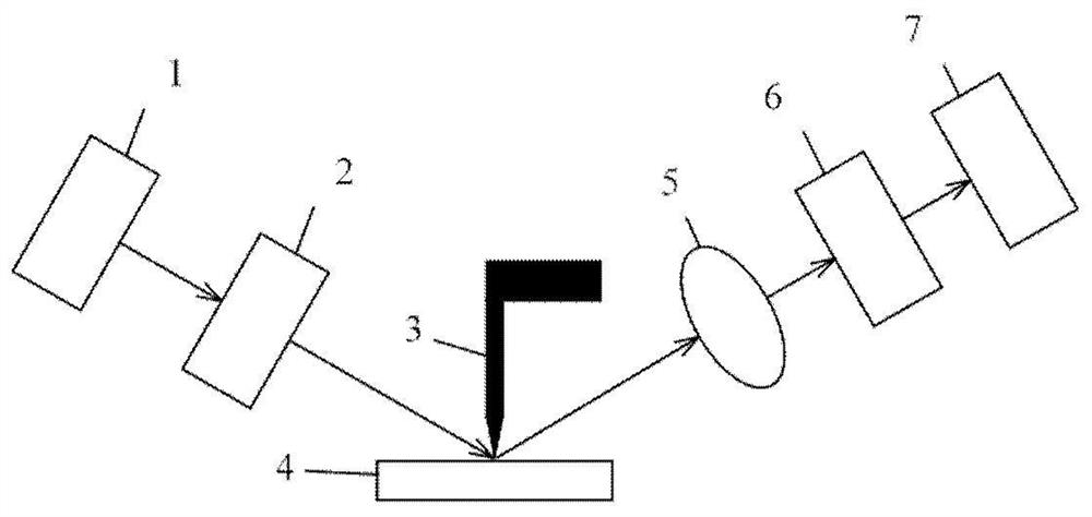
[0058] exist figure 1 A near-field optical polarization spectrometer according to a first embodiment of the present invention is shown in . As shown in Figure 1, the near-field optical polarization spectrometer includes an incident light generation module (light source 1, polarization generation device 2), a probe scanning microscope module 3, a sample 4, an outgoing light detection module (first focusing device 5, polarization Detection device 6, detection device 7). The polarization generating device 2 and the polarization detecting device 6 can also decide whether to rotate according to actual needs, and form R.P. (rotating polarization generating device 2), R.A. (rotating polarization detecting device 6), and the two devices rotate according to a certain frequency ratio.

[0059] The light emitted by the light source 1 is modulated by the polarization generating device 2 into probe light of different polarization states, which is incident on the probe tip of the probe sca...

no. 2 example

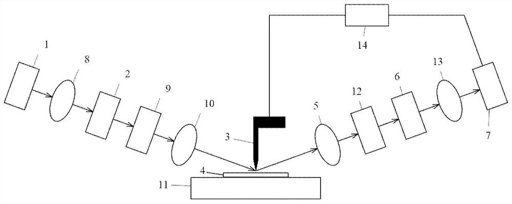
[0070] exist figure 2 A near-field optical polarization spectrometer according to a second embodiment of the present invention is shown in . As shown in Figure 2, the near-field optical polarization spectrometer includes an incident light generating module (light source 1, second focusing device 8, polarization generating device 2, first phase compensating device 9, third focusing device 10), a probe scanning display Micro module 3, sample 4, motorized platform system 11, outgoing light detection module (first focusing device 5, second phase compensation device 12, polarization detection device 6, fourth focusing device 13, detection device 7, lock-in amplifier 14) . Polarization generation device 2, first phase compensation device 9, second phase compensation device 12 and polarization detection device 6 decide whether to use according to actual needs, can form PSA (polarization generation device 2-sample 4-polarization detection device 6), PSCA ( Polarization generation d...


PUM


Abstract

The invention discloses a near-field optical polarization spectrometer. The near-field optical polarization spectrometer comprises an incident light generation module, a probe scanning microscopic module and an emergent light detection module; the incident light generation module emits detection light in different polarization states; an incident light beam enters a probe tip of the probe scanning microscopic module; the detection light interacts with a micro-nano space structure formed by the probe tip and a surface of a sample, the polarization state of the detection light changes, then scattered light, transmission light or reflected light of the light beam is collected by the emergent light detection module; the change information generated by the polarization state in the interaction is obtained by demodulating the polarization state of emergent light; inversion calculation is carried out on the information to obtain related information of the tested sample. According to the spectrometer of the invention, nanoscale ultrahigh transverse spatial resolution can be realized, the requirement of a semiconductor key device for precise measurement of nanoscale dimensions is met. The spectrometer has the advantages of non contact with the sample, no damage to the sample and the like.

Description

technical field [0001] The invention relates to the technical field of spectrometer testing, in particular to a near-field optical polarization spectrometer. Background technique [0002] With the development of semiconductor manufacturing technology, the critical dimensions of semiconductor devices are continuously shrinking, and the 5nm node has been realized. At the same time, the semiconductor manufacturing industry has higher and higher requirements for lateral spatial resolution of device size measurement. The parameters measured by the traditional polarization spectrometer are the average value of the light spot formed by the probe light on the surface of the tested sample. Although the vertical resolution of traditional polarimeters depends on the phase measurement sensitivity of the instrument, and generally can achieve Angstrom level, the lateral resolution of polarimeters is limited by the spot size, and the spot size diameter of micro-spot type polarimeters is be...

Claims


Application Information

Patent Timeline
IPC IPC(8): G01J3/447G01N21/21G01B11/06
CPCG01J3/447G01N21/21G01N21/211G01B11/0641G01N2021/213
Inventor 张凌云刘涛王玥陈楠李磊王博雨冷兴龙赵丽莉李楠刘键景玉鹏何萌夏洋
Owner INST OF MICROELECTRONICS CHINESE ACAD OF SCI
Learn More