Optical fiber liquid viscosity coefficient measuring device

A technology of viscosity coefficient and measuring device, which is applied in the direction of measuring device, indirect flow characteristic measurement, flow characteristic, etc., can solve the problem of low accuracy, and achieve the effect of high measurement accuracy and good application prospect

Inactive Publication Date: 2021-12-03
陕西咖润特光电科技有限公司
View PDF0 Cites 0 Cited by
  • Summary
  • Abstract
  • Description
  • Claims
  • Application Information

AI Technical Summary

Problems solved by technology

These measurement methods rely on purely mechanical means, and the measurement accuracy is low

Method used


Image

  • Optical fiber liquid viscosity coefficient measuring device
  • Optical fiber liquid viscosity coefficient measuring device

Examples


Embodiment 1

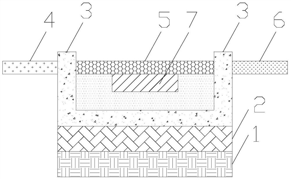
[0021] The invention provides an optical fiber liquid viscosity coefficient measuring device. Such as figure 1 As shown, the optical fiber liquid viscosity measurement device includes a base 1 , a vibration source 2 , a square groove 3 , an optical fiber, and a force plate 7 . The vibration source 2 is placed on the base 1, the base 1 is used to support the vibration source 2, and the vibration source 2 is used to generate vibration. The direction of vibration can be horizontal or vertical. In order to improve the accuracy of the measurement, the change of the optical fiber propagation coefficient is measured in different vibration directions, and the viscosity coefficient of the liquid is deduced in each case, and then the average value is taken. The square tank 3 is placed on the vibration source 2, and under the action of the vibration source 2, the liquid in the square tank 3 vibrates. The core idea of ​​the invention can also be realized when the groove is of general s...

Embodiment 2

[0025] On the basis of Embodiment 1, the diameter of the sensitive part 5 is smaller than the diameters of the incident part 4 and the outgoing part 6 . In this embodiment, the sensitive part 5 is not a grating fiber. Specifically, the coating layer of the sensitive part 5 is thinner than that of the incident part 4 and the outgoing part 6 , so that the diameter of the sensitive part 5 is smaller than the diameters of the incident part 4 and the outgoing part 6 . In this way, under the action of the force plate 7, the sensitive part 5 is more likely to be bent, thereby changing the transmission characteristics of the optical fiber more, thereby realizing a higher accuracy measurement of the viscosity coefficient of the liquid.

[0026] Furthermore, the core diameter of the sensitive part 5 is also smaller than the core diameters of the incident part 4 and the outgoing part 6 . In this way, when the sensitive part 5 bends, the propagation characteristics of the sensitive part ...

Embodiment 3

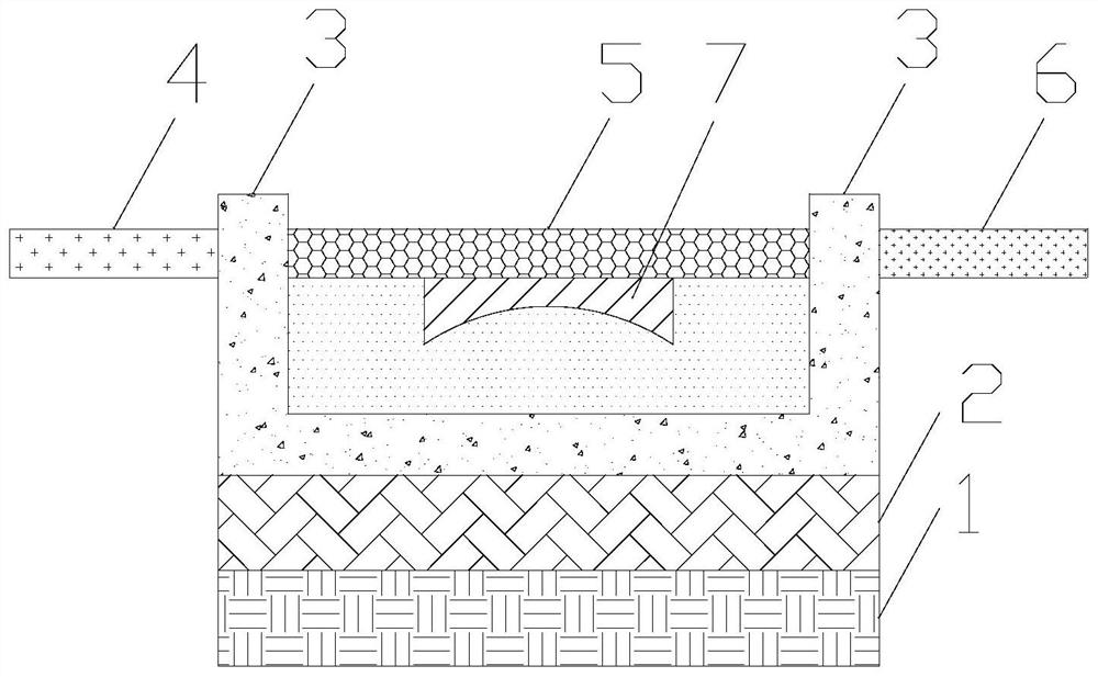
[0028] On the basis of Embodiment 1 or 2, the bottom surface of the force plate 7 is concave. That is to say, the surface of the force receiving plate 7 in contact with the liquid surface is concave. In this way, on the one hand, when the vibration source 2 vibrates in the vertical direction, the concave shape is more consistent with the shape of the wave crest, so that the liquid can have more effects on the force plate 7, so that the force plate 7 is sensitive to changes On the other hand, when the vibration source generates vibration in the horizontal direction, the area of ​​action between the concave shape and the liquid is larger, so that the force generated by the liquid on the force plate 7 is greater, thus changing more Propagation characteristics of the sensitive part 5. Therefore, this embodiment can realize higher accuracy measurement of liquid viscosity coefficient.


PUM


Abstract

The invention relates to the field of liquid viscosity coefficient measurement, in particular to an optical fiber liquid viscosity coefficient measuring device which comprises a substrate, a vibration source, a square groove, an optical fiber and a stress plate. During application, liquid to be measured is placed in the square groove, and the liquid level is in contact with the stress plate. The vibration source generates vibration, the liquid forms standing waves in the square groove, the stress plate is acted by the liquid, the propagation characteristic of the optical fiber is changed, and the liquid viscosity coefficient is measured by detecting the change of the optical propagation characteristic of the optical fiber. The propagation characteristic of light in the optical fiber seriously depends on the morphology parameters of the optical fiber, so that the device has the advantage of high liquid viscosity coefficient measurement accuracy, and has a good application prospect in the field of liquid viscosity coefficient measurement.

Description

technical field [0001] The invention relates to the field of liquid viscosity measurement, in particular to an optical fiber liquid viscosity measurement device. Background technique [0002] The viscosity coefficient of a liquid, also known as viscosity, is an important physical quantity describing the internal friction properties of a liquid. The viscosity coefficient characterizes the ability of the liquid to resist deformation when the liquid is in relative motion. The viscosity coefficient depends on the material itself and its temperature. [0003] Traditional methods for measuring the viscosity coefficient include the falling ball method, capillary method, and rotating drum method. These measurement methods rely on purely mechanical means, and the measurement accuracy is low. Contents of the invention [0004] In order to solve the above problems, the present invention provides a fiber optic liquid viscosity measuring device, comprising: a base, a vibration sourc...

Claims


Application Information

Patent Timeline
Patent Type & Authority Applications(China)
IPC IPC(8): G01N11/00
CPCG01N11/00G01N2011/008
Inventor 牛艳娜张中侠
Owner 陕西咖润特光电科技有限公司
Why Eureka
Try Eureka