High-sensitivity rotating speed detection device

A speed detection and sensitive technology, applied in the mechanical field, can solve the problems of increasing the cost of the detection device, achieve the effects of small force, good application prospects, and reduced wear

Inactive Publication Date: 2022-04-15
金华伏安光电科技有限公司
View PDF0 Cites 0 Cited by
  • Summary
  • Abstract
  • Description
  • Claims
  • Application Information

AI Technical Summary

Problems solved by technology

[0004] When the speed of the object selection is high, the existing rotational speed measurement method puts forward higher requirements on the response speed of the electrical signal acquisition element, thus increasing the cost of the detection device

Method used


Image

  • High-sensitivity rotating speed detection device
  • High-sensitivity rotating speed detection device

Examples


Embodiment 1

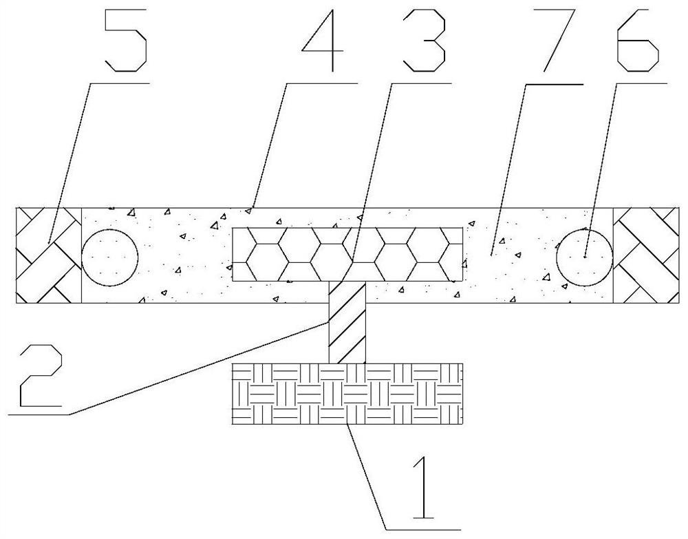
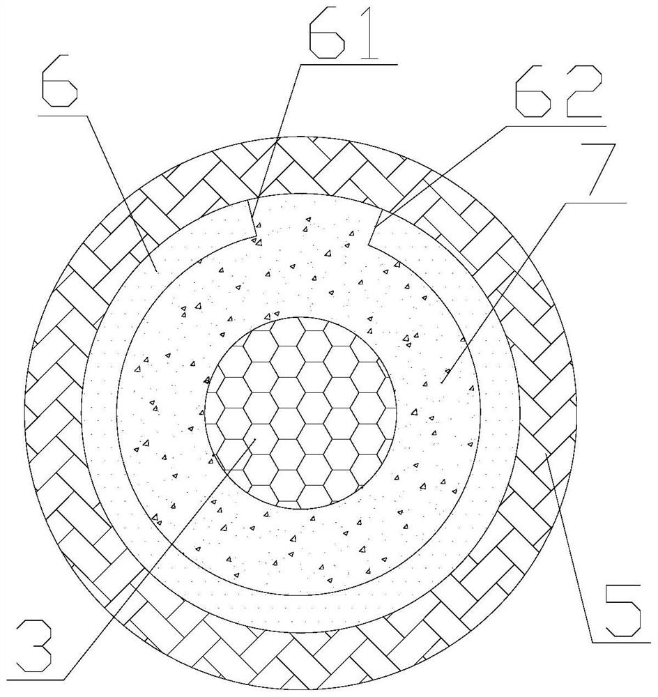
[0021] The invention provides a highly sensitive rotational speed detection device. Such as figure 1 and figure 2 As shown, the high-sensitivity speed detection device includes a fixed part 1 , a rotating shaft 2 , a rotating disk 3 , a sensor box 4 , an elastic layer 5 , an optical fiber 6 , and a fluid 7 . The material of the sensing box 4 is stainless steel. The material of the rotating shaft 2 is stainless steel or other solid materials, which is not specifically limited here. The rotating shaft 2 runs through the bottom surface of the sensing box 4 , one end of the rotating shaft 2 is fixedly connected to the fixed part 1 , and the other end of the rotating shaft 2 is fixedly connected to the rotating disk 3 in the sensing box 4 . The material of the rotating disk 3 is stainless steel. The cross section of the sensing box 4 is circular, and the cross section of the rotating disk 3 is circular. When rotating, the rotating disk 3 is not in contact with the sensor box ...

Embodiment 2

[0027] On the basis of Embodiment 1, the optical fiber 6 includes a grating optical fiber. That is to say, the optical fiber 6 contains at least one section of grating fiber. Under the action of the centrifugal force of the fluid 7, the grating fiber is elongated, so that the center wavelength of the grating fiber is red-shifted. The rotational speed is determined by measuring the movement of the center wavelength of the grating fiber. Furthermore, the optical fiber 6 includes two sections of grating optical fibers with different central wavelengths. In this way, when the optical fiber 6 is elongated by centrifugal force, the central wavelengths of the two sections of the grating optical fiber are moved. The rotational speed of the object to be measured can be obtained by the difference between the two center wavelengths, and the experimental data processing is simple.

Embodiment 3

[0029] On the basis of Embodiment 2, the edge of the rotating disk 3 is toothed, and the teeth are distributed around the rotating disk 3 . In this way, the interaction between the rotating disk 3 and the fluid 7 is enhanced, so that the fluid 7 rotates at a faster speed, generates greater centrifugal force, changes the optical fiber 6 to a greater extent, and improves the sensitivity of rotational speed detection. The rotating disk 3 does not have chirality, so that when the object to be measured rotates in the opposite direction, the present invention can also accurately measure the rotational speed. Furthermore, the length of the teeth is adjustable. When the object to be measured rotates fast, the teeth are short, and the force on the optical fiber 6 is small; when the object to be measured rotates slowly, the teeth are long, and the force on the optical fiber 6 is large. Therefore, the length of the tooth can be adjusted so that this embodiment has a wider measurement ra...


PUM


Abstract

The invention relates to the field of machinery, in particular to a high-sensitivity rotating speed detection device which comprises a fixing part, a rotating shaft, a rotating disc, a sensing box, an elastic layer, an optical fiber and a fluid, the rotating shaft penetrates through the sensing box, one end of the rotating shaft is fixedly connected with the fixing part, the other end of the rotating shaft is fixedly connected with the rotating disc in the sensing box, and the rotating disc is arranged in the middle of the sensing box. The elastic layer is arranged on the inner side of the sensing box, the optical fiber is fixed on the inner side of the elastic layer, the two ends of the optical fiber are provided with an optical fiber input end and an optical fiber output end, and a gap is formed between the rotating disc and the optical fiber and filled with fluid. During application, the device is fixed on an object to be measured through the fixing part. An object to be detected drives the rotating disk and the fluid to rotate through the rotating shaft, centrifugal force of the fluid acts on the optical fiber, propagation characteristics of the optical fiber are changed, and rotating speed detection is achieved through changes of the propagation characteristics. According to the invention, rotation speed measurement of high rotation speed can be realized, and the method has good application prospects in the field of high rotation speed measurement.

Description

technical field [0001] The invention relates to the mechanical field, in particular to a highly sensitive rotational speed detection device. Background technique [0002] Speed ​​is an important characteristic parameter in performance testing, and many characteristic parameters of mechanical devices are inseparable from functions related to speed. Speed ​​detection refers to the measurement of the speed of object rotation, and speed detection is a key point in various fields of industrial production. [0003] Common speed measurement methods include Hall element type and photoelectric code disc type. As the name implies, this method uses Hall switch elements to measure the speed. The Hall element speed measurement method is to install a disk on the object to be measured, and there are several pairs of small magnets on the disk. The more small magnets, the higher the resolution. The Hall switch is fixed near the small magnets. When the motor When rotating, the small magnet...

Claims


Application Information

Patent Timeline
Patent Type & Authority Applications(China)
IPC IPC(8): G01P3/36
Inventor 张中侠王勇凯
Owner 金华伏安光电科技有限公司
Why Eureka
Try Eureka