Method for correcting tilt error of workpiece table and photoetching device

A technology of tilt error and workpiece table, which is applied in the exposure device of photolithography process, microlithography exposure equipment, optics, etc., can solve the problem of low measurement accuracy, achieve high calibration accuracy, reduce mechanical error, and improve accuracy.

Active Publication Date: 2021-12-03
SHANGHAI MICRO ELECTRONICS EQUIP (GRP) CO LTD
View PDF5 Cites 0 Cited by
  • Summary
  • Abstract
  • Description
  • Claims
  • Application Information

AI Technical Summary

Problems solved by technology

[0008] What the present invention aims to solve is the problem of how to correct the inclination error of the workpiece table when the measurement accuracy of the vertical position of the focusing and leveling sensor in the prior art is low even when there is no focusing and leveling sensor

Method used


Image

  • Method for correcting tilt error of workpiece table and photoetching device
  • Method for correcting tilt error of workpiece table and photoetching device
  • Method for correcting tilt error of workpiece table and photoetching device

Examples


Embodiment 1

[0080] This embodiment provides a method for correcting the tilt error of the workpiece table, which is used for correcting the tilt error when the workpiece table moves in the Y direction. In this embodiment, as attached Figure 4 As shown, it is a schematic diagram of the calibration marks provided on the mask in this embodiment. It can be seen from the figure that the sub-marks 201 of the calibration marks are distributed in N rows×M columns, where N≧2. The row distribution of the sub-marks 201 is consistent with the X direction, and the column distribution of the sub-marks 201 is consistent with the Y direction. For ease of description, in this embodiment, N=3 is taken as an example for description, which is obviously not a limitation of the present invention.

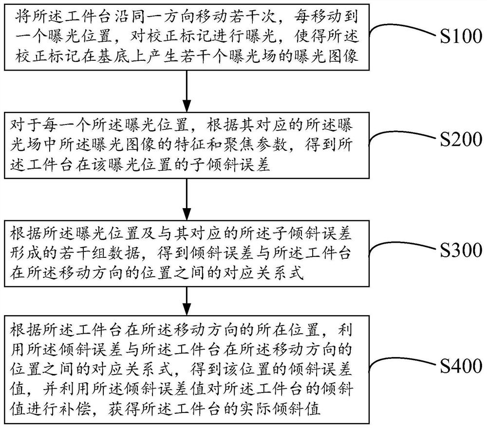
[0081] A method for correcting the inclination error of the workpiece table provided in this embodiment includes the following four steps of S100, S200, S300 and S400.

[0082] S100: Move the workpiece table seve...

Embodiment 2

[0094] The method for correcting the inclination error of the workpiece table provided in this embodiment is used for correcting the inclination error of the workpiece table when it moves in the X direction. In this embodiment, as attached Figure 6 As shown, it is a schematic diagram of the calibration marks provided on the mask in this embodiment. It can be seen from the figure that the sub-marks 202 of the calibration marks are distributed in N rows×M columns, where M≥2. The row distribution of the sub-marks 202 is consistent with the X direction, and the column distribution of the sub-marks 202 is consistent with the Y direction. For the convenience of description, in this embodiment, M=3 (in this embodiment, there are 3 columns of submarks) is taken as an example for illustration, obviously, this is not a limitation of the present invention.

[0095] A method for correcting the inclination error of the workpiece table provided by this implementation includes the followin...


PUM


Abstract

The invention provides a method for correcting a tilt error of a workpiece table and a photoetching device, and the correction method comprises the following steps: moving the workpiece table for a plurality of times along the same direction, so as to enable a correction mark to generate exposure images of a plurality of exposure fields on a substrate; for each exposure field, obtaining a sub-tilt error at each exposure position according to the characteristics and focusing parameters of the exposure image; according to the sub-tilt error and the exposure position, obtaining a corresponding relational expression between the tilt error and the position of the workpiece table in the moving direction; and correcting the workpiece table accordingly. According to the method for correcting the inclination error of the workpiece table, the inclination deviation in the movement process of the workpiece table can be conveniently obtained, and the positioning accuracy of the workpiece table is improved. The method can be used when no focusing and leveling sensor is arranged at the exposure position, the repeatability of the vertical position of the mark obtained through alignment measurement is better than that of the vertical position measured by the focusing and leveling sensor, the calibration precision is higher, and the precision of the photoetching machine system is improved.

Description

technical field [0001] The invention relates to the technical field of semiconductors, in particular to a method for correcting the inclination error of a workpiece table and photolithography equipment. Background technique [0002] A projection lithography machine is a device that projects the pattern on the mask onto the upper surface of the substrate through the objective lens. Usually, it is necessary to calibrate the workpiece stage of the lithography machine to ensure that the mask pattern can be projected to the correct position on the substrate surface according to the design requirements. [0003] as attached figure 1 As shown, if there is surface irregularity or deformation in the Y direction of the strip mirror, the interferometer model will be figure 1 In the normal state 102 where the workpiece table is not tilted, it is mistaken for the workpiece table to be in the tilted state, and the workpiece table is adjusted to the tilted state 101 . Therefore, the inc...

Claims


Application Information

Patent Timeline
Patent Type & Authority Applications(China)
IPC IPC(8): G03F7/20
CPCG03F7/70725G03F7/7085
Inventor 杨泽雷
Owner SHANGHAI MICRO ELECTRONICS EQUIP (GRP) CO LTD
Why Eureka
Try Eureka