
Mining area target identification method based on fusion of fisheye camera and laser radar

A technology of laser radar and fisheye camera, which is applied in the field of environmental perception, can solve the problems of incomplete fusion, large degree of information loss, poor correction effect, etc., and achieve the effect of reducing hardware cost, complete feature extraction, and improving effectiveness

Pending Publication Date: 2021-12-03
BEIHANG UNIV
View PDF2 Cites 2 Cited by
  • Summary
  • Abstract
  • Description
  • Claims
  • Application Information

AI Technical Summary

Problems solved by technology

[0008] 1. The industrial-grade fisheye camera used in the mining area has a large degree of distortion, and the distortion correction effect of the traditional isometric model is poor. Except for the central part, the pixels on the edge of the image have a large degree of stretching problem
[0009] 2. The distribution of the point cloud directly on the fisheye image will be uneven, especially the point cloud at the edge of the image is more sparse, and the feature extraction effect is very small
[0010] 3. The update frequency of the fisheye camera and lidar is very different, and there is a matching error between the images captured at different frame rates and the point cloud, which makes it impossible to perform subsequent feature extraction and target recognition network training
[0011] 4. The fusion of fisheye camera and lidar is cross-dimensional heterogeneous sensor fusion. The current fusion method has a large degree of information loss and incomplete fusion

Method used


Image

  • Mining area target identification method based on fusion of fisheye camera and laser radar
  • Mining area target identification method based on fusion of fisheye camera and laser radar
  • Mining area target identification method based on fusion of fisheye camera and laser radar

Examples


Embodiment Construction

[0073] The specific embodiments of the present invention will be described in detail below in conjunction with the accompanying drawings, but it should be understood that the protection scope of the present invention is not limited by the specific embodiments.

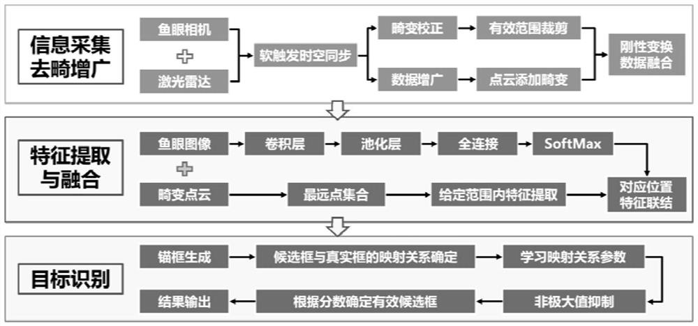
[0074] like figure 1 As shown, the present invention proposes a mining area target recognition method based on fisheye camera and laser radar fusion, and its steps include three steps: 1) information collection, de-distortion augmentation; 2) feature extraction and fusion; 3) two Stage object recognition network construction. The three steps present a serial relationship, all of which lay the foundation for the execution of the next step.

[0075] 1) Information collection, distortion correction and data augmentation:

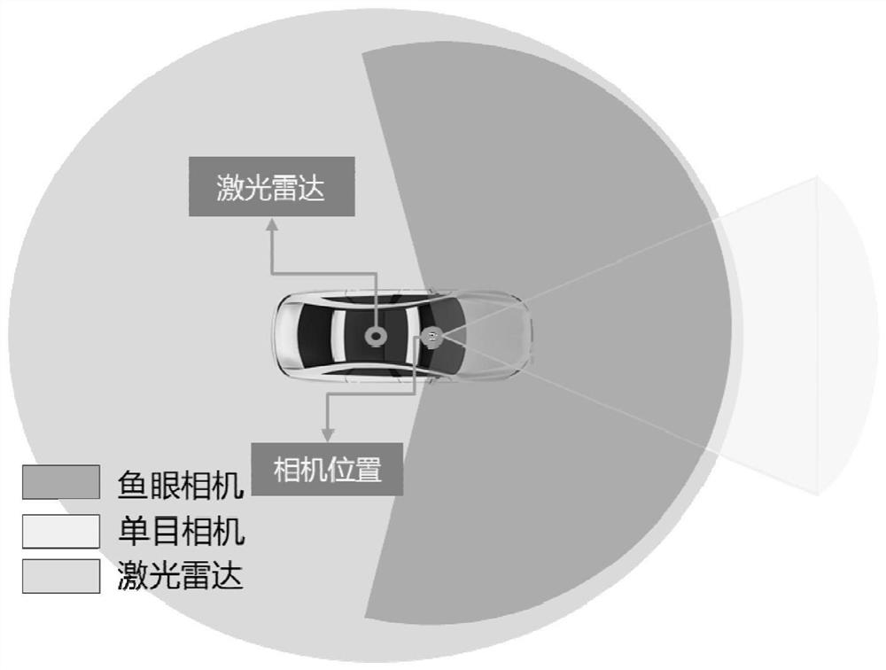
[0076] It is divided into two branches: image acquisition based on fisheye camera and point cloud acquisition based on lidar, to obtain real-time environmental information during driving in the mining...


PUM


Abstract

The invention provides a mining area target identification method based on fusion of a fisheye camera and a laser radar. The mining area target identification method comprises the following steps: 1) carrying out information acquisition, distortion correction and data augmentation; 2) feature extraction and fusion: performing feature extraction on the data subjected to distortion correction and data augmentation by using different branches, and then performing fusion output on the features of the two kinds of data through a bilinear interpolation-based method; and 3) target identification: using a classic RPN structure, and performing result output through several important steps of generating an anchor frame, determining a mapping relationship between the anchor frame and a real frame, mapping parameter learning, non-maximum suppression and determining an effective candidate frame according to a score. The advantages of the two are integrated, the recognition performance of unmanned driving in a mining area environment is effectively improved by using a fusion mode, rich, real-time and accurate target pose information is provided for a subsequent decision control module, and unmanned driving landing is assisted.

Description

technical field [0001] The present invention relates to the technical field of environmental perception, and in particular to a mine area target recognition method based on the fusion of a fisheye camera and a laser radar, which is applied to the perception of vehicle driving environment in a mine area scene. Background technique [0002] Autonomous driving technology has developed rapidly in recent years, and the technology has been implemented in some specific scenarios at home and abroad. Because the mining area has the characteristics of a closed environment, relatively fixed transportation roads, and slow vehicle speeds, it has become one of the most suitable scenarios for the implementation of autonomous driving technology that has attracted much attention. As the basis of autonomous driving research, perception technology provides rich environmental information for subsequent control and decision-making modules. Target recognition is an important part of perception t...

Claims


Application Information

Patent Timeline
IPC IPC(8): G06K9/62G06T3/00G06T5/00G01S7/48
CPCG01S7/4802G06T2207/10004G06F18/22G06F18/253G06T3/047G06T5/80Y02A90/10
Inventor 余贵珍崔洁茗周彬江泽鑫刘蓬菲
Owner BEIHANG UNIV
Learn More