Supercharge Your Innovation With Domain-Expert AI Agents!

Non-contact micro-current measurement system based on Rogowski coil

A Rogowski coil and non-contact technology, which is applied in the field of non-contact micro current measurement system, can solve problems such as being susceptible to external interference, small voltage signal, difficult to measure accurately, etc.

Active Publication Date: 2021-12-03
SOUTHWEST JIAOTONG UNIV
View PDF13 Cites 0 Cited by
  • Summary
  • Abstract
  • Description
  • Claims
  • Application Information

AI Technical Summary

Problems solved by technology

Due to many technical difficulties, for example, in the case of low current, the voltage signal induced by the existing Rogowski coil is very small and very unstable, and it is extremely susceptible to external interference and difficult to measure accurately
Therefore, the prior art fails to realize the accurate measurement of tiny currents using Rogowski coils in the physical laboratory.

Method used


Image

  • Non-contact micro-current measurement system based on Rogowski coil
  • Non-contact micro-current measurement system based on Rogowski coil
  • Non-contact micro-current measurement system based on Rogowski coil

Examples


Embodiment 1

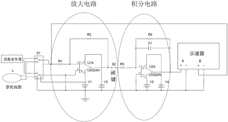
[0092] Such as figure 1 As shown, the circuit simulation software is used for simulation analysis, and the analog function signal generator is used to simulate the output voltage signal of the Rogowski coil (ie figure 1 Turn on the function generator with switch S1); set the frequency of the function signal generator in the simulation software as f =1000 Hz, the amplitude parameter is A =0.2 mV, close the switches S1 and S2, and start the simulation;

[0093] Such as Figure 5 As shown, open the analog oscilloscope of the simulation software, and obtain the simulation results on the analog oscilloscope.

[0094] Among them, the display parameters of the analog oscilloscope are set as follows: in the horizontal direction, each large division represents 0.5 ms; in the vertical direction, each large division represents 0.2 mV; from Figure 5 It can be seen that the simulation result is a sinusoid with an amplitude of 0.2 mV, a frequency of 1000 Hz, and a DC component of 0; ...

Embodiment 2

[0096] To set up the measurement system, use the AC voltage output by a function signal generator, connect a 50 Ω load resistor in series, and pass the closed loop wire through the Rogowski coil in a non-contact manner. By adjusting the output voltage of the function signal generator, the magnitude of the current passing through the Rogowski coil can be changed.

[0097] When the current passing through the Rogowski coil is set to be 0.2 mA, that is, when the output voltage of the function signal generator is 0.01 V, it is measured from the oscilloscope. One large division is 0.2 mV. By recording, a sinusoidal signal with an amplitude of 0.22 mV and a frequency of 1000 Hz was obtained on the oscilloscope; compared with the input current amplitude of 0.2 mA, it can be proved that the designed circuit can recover the original output current amplitude signal.

[0098] In order to further illustrate the applicability of the designed circuit, without changing the value of the load...


PUM

PropertyMeasurementUnit
Coil turnsaaaaaaaaaa
Capacitanceaaaaaaaaaa

Abstract

The invention relates to the technical field of circuit experiment equipment, in particular to a non-contact micro-current measurement system based on a Rogowski coil. The system comprises a Rogowski coil, an amplifying circuit module, an integrating circuit module and an oscilloscope, and is characterized in that a to-be-measured current unit passes through the middle portion of the Rogowski coil, the Rogowski coil is used for detecting the current signal of the to-be-measured current unit, the amplifying circuit module is used for amplifying the signal, and the integrating circuit module is used for carrying out integral reduction processing on the current amplifying signal to obtain a current reduction signal. According to the invention, the Rogowski coil is used for detecting the current signal of the to-be-measured current unit, the detected signal is amplified through the amplifying circuit module, and then the integrating circuit module is used for integral reduction, so that the precise measurement of the micro current is realized, the possibility is provided for the non-contact measurement of the micro current in a common physical experiment environment, and the method has important significance on physical experiment teaching research.

Description

technical field [0001] The invention relates to the technical field of circuit experiment equipment, in particular to a non-contact tiny current measurement system based on a Rogowski coil. Background technique [0002] In engineering, Rogowski coils are widely used in large current detection of instruments and equipment under various conditions. For example, the journal "Electronic Devices" published a technical document titled "Research on Ultra-Large Current Detection Technology for High-Power Pulse Power Supply" on page 322 in the second issue of 2020. Ultra-large current detection for high-power pulsed power supply systems". Another example is the technical literature titled "Rogowski coil structure optimization design based on improved genetic algorithm and finite element analysis" published in the 22nd issue of "Science Technology and Engineering" in 2020 on pages 9075-9080. The current at the outlet end of the low-voltage side of the furnace transformer passes thro...

Claims


Application Information

Patent Timeline
IPC IPC(8): G09B23/18
CPCG09B23/183
Inventor 胡远扬樊代和张怡然杨浩唐晓凡倪俊哲任宸旸贾欣燕
Owner SOUTHWEST JIAOTONG UNIV
Features
  • R&D
  • Intellectual Property
  • Life Sciences
  • Materials
  • Tech Scout
  • Unparalleled Data Quality
  • Higher Quality Content
  • 60% Fewer Hallucinations
Learn More