PWM relay control circuit
A relay control and relay technology, applied in the aviation field, can solve the problems of increasing design cost, maintaining low energy, and high driving voltage, achieving the effect of saving energy consumption and solving high energy loss
- Summary
- Abstract
- Description
- Claims
- Application Information
AI Technical Summary
Problems solved by technology
Method used
Image

Examples
Embodiment 1
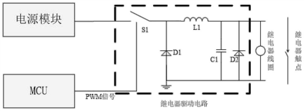
[0019] Such as figure 1 As shown, a PWM relay control circuit is connected to the relay coil, connected to the power module, and connected to the MCU, including:
[0020] MCU module, used to output PWM waveforms with different duty ratios;
[0021] Power module for single power output;
[0022] The relay driving circuit is connected with the PWM signal of the power module and the MCU module, and is used to control the driving voltage of the relay coil to control the on and off of the relay.
[0023] The power supply module provides high-voltage power supply, and the voltage can be reduced through the duty cycle.
[0024] By adjusting the duty cycle of the PWM signal to adjust the relay driving voltage so that the relay has a high voltage at the moment of turning on, and the driving voltage is reduced during the relay maintenance period, thus saving unnecessary energy consumption of the relay after starting, and thus solving the problem of relay absorption. There is a proble...
Embodiment 2
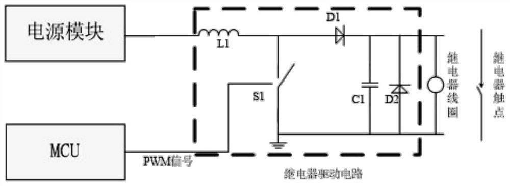
[0030] Such as figure 2 As shown, a PWM relay control circuit is connected to the relay coil, connected to the power module, and connected to the MCU, including:
[0031] MCU module, used to output PWM waveforms with different duty ratios;
[0032] Power module for single power output;
[0033] The relay driving circuit is connected with the PWM signal of the power module and the MCU module, and is used to control the driving voltage of the relay coil to control the on and off of the relay.
[0034] By adjusting the duty cycle of the PWM signal to adjust the relay driving voltage so that the relay has a high voltage at the moment of turning on, and the driving voltage is reduced during the relay maintenance period, thus saving unnecessary energy consumption of the relay after starting, and thus solving the problem of relay absorption. There is a problem of high energy loss after the combination.
[0035] The relay drive circuit adjusts the relay drive voltage by adjusting ...
Embodiment 3
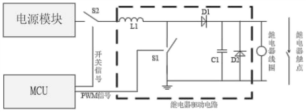
[0042] Such as image 3 As shown, a PWM relay control circuit is connected with the relay coil, connected with the S2 switch, and connected with the MCU, including:
[0043] MCU module, used to output PWM waveforms with different duty ratios;
[0044] Power module for single power output;
[0045] The relay driving circuit is connected with the PWM signal of the power module and the MCU module, and is used to control the driving voltage of the relay coil to control the on and off of the relay.
[0046] By adjusting the duty cycle of the PWM signal to adjust the relay driving voltage so that the relay has a high voltage at the moment of turning on, and the driving voltage is reduced during the relay maintenance period, thus saving unnecessary energy consumption of the relay after starting, and thus solving the problem of relay absorption. There is a problem of high energy loss after the combination.
[0047] The relay drive circuit adjusts the relay drive voltage by adjustin...
PUM
 Abstract
Description
Claims
Application Information
 - R&D
- Intellectual Property
- Life Sciences
- Materials
- Tech Scout
- Unparalleled Data Quality
- Higher Quality Content
- 60% Fewer Hallucinations
Browse by: Latest US Patents, China's latest patents, Technical Efficacy Thesaurus, Application Domain, Technology Topic, Popular Technical Reports.
© 2025 PatSnap. All rights reserved.Legal|Privacy policy|Modern Slavery Act Transparency Statement|Sitemap|About US| Contact US: help@patsnap.com