Current-limiting protection circuit of bipolar process switching power supply

A switching power supply, current-limiting protection technology, applied in electrical components, output power conversion devices, etc., can solve problems such as current-limiting protection design limitations, avoid false triggering, and improve circuit details.

Active Publication Date: 2021-12-03
NANJING MICRO ONE ELECTRONICS
View PDF7 Cites 2 Cited by
  • Summary
  • Abstract
  • Description
  • Claims
  • Application Information

AI Technical Summary

Problems solved by technology

Process characteristics make curren

Method used


Image

  • Current-limiting protection circuit of bipolar process switching power supply
  • Current-limiting protection circuit of bipolar process switching power supply
  • Current-limiting protection circuit of bipolar process switching power supply

Examples


Embodiment Construction

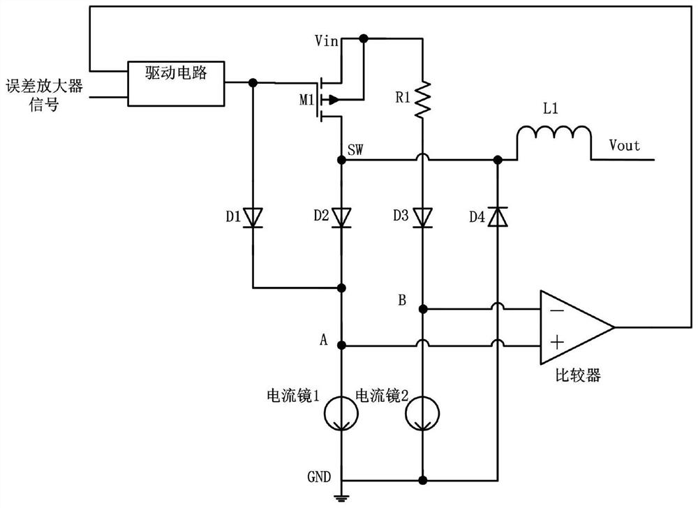
[0017] see figure 2 , including the input power supply Vin, the ground potential GND, the switching power supply internally includes the error amplifier signal and the drive circuit, the driven MOS tube is the PMOS power tube M1, the resistor R1, the diodes D1, D2 and D3, the current mirror 1 and the current mirror 2 and Comparators. The power transistor M1 of the switching power supply circuit is in a state of continuous switching when it is working. Let the potential of one end of the comparator connected to the current mirror 1 be V A , the potential of one end of the comparator connected to the current mirror 2 is V B , the diode conduction voltage drop is V D , the input power supply voltage is Vin, the current flowing into the current mirror 1 is I1, the current flowing into the current mirror 2 is I2, the current flowing through the power tube M1 is Imos, and the on-resistance of the power tube M1 is Rdson. When the gate of PMOS power transistor M1 is at a high pot...


PUM


Abstract

The invention provides a current-limiting protection circuit of a bipolar process switching power supply. The constant current generated by a current mirror flows through a resistor to obtain resistance voltage drop, and the resistance voltage drop is compared with conduction voltage drop of a power MOS (Metal Oxide Semiconductor) tube to judge whether the current of the power tube exceeds a set maximum value or not, so that the grid voltage of the power MOS tube is adjusted to play a current-limiting role. The invention provides a current-limiting protection design mode which is simple in structure and low in power consumption for a switching power supply system using a bipolar process circuit to drive a power MOS (Metal Oxide Semiconductor) tube. By setting the proportional relation between the resistor and the voltage drop of the MOS tube, the current-limiting protection threshold value can be accurately and flexibly set, and adjustment and design are facilitated. The defect that efficiency is affected by resistance loss due to the fact that a traditional circuit adopts a trigger mode of outputting series resistance sampling resistance drop is overcome.

Description

technical field [0001] The invention relates to a switching power supply, in particular to a current-limiting protection circuit of a bipolar switching power supply, and belongs to the technical field of integrated circuit power supply design. Background technique [0002] In the switching power supply chip, when the system output current is greater than the maximum input current threshold of the design parameters, the power tube current needs to be limited to prevent the chip from being damaged by the large current. For circuits designed entirely in CMOS technology, the current-limiting protection technology is very mature, and there are many excellent circuits to choose from. For a system structure in which the control circuit is a bipolar circuit and the power tube is an external MOS tube, the traditional method is to connect a small resistor in series at the output end, and judge whether the output current exceeds the design threshold by sampling its resistance voltage d...

Claims


Application Information

Patent Timeline
IPC IPC(8): H02M1/32H02M1/08
CPCH02M1/32H02M1/08Y02B70/10
Inventor 于圣武李海龙黄桦
Owner NANJING MICRO ONE ELECTRONICS
Why Eureka
Try Eureka