Power failure holding circuit and control method

A technology of power-down retention and control methods, applied to electrical components, conversion equipment without intermediate conversion to AC, output power conversion devices, etc., can solve the problem of slow dynamic response of mode switching, fast switching response speed, narrow application range, etc. problem, to achieve the effect of fast switching response, wide application range and simple control

Pending Publication Date: 2021-12-03
MORNSUN GUANGZHOU SCI & TECH
View PDF6 Cites 6 Cited by
  • Summary
  • Abstract
  • Description
  • Claims
  • Application Information

AI Technical Summary

Problems solved by technology

[0006] In view of this, the present invention proposes a power-down holding circuit and a control method. The power-down holding circuit can work in boost, buck, and free discharge modes, and the boost and buck modes are controlled by a separate switch tube, and the up and down The switching response speed of the pressure mode is fast, which can effectively solve the problems of narrow application range, complex control and slow dynamic response of mode switching in the existing technology

Method used


Image

  • Power failure holding circuit and control method
  • Power failure holding circuit and control method
  • Power failure holding circuit and control method

Examples


no. 1 example

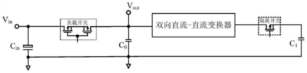
[0032] Please refer to Figure 4 , the power-fail holding circuit of this embodiment is used to connect between the output terminal of the power supply of the previous stage and the input terminal of the switching power supply of the subsequent stage, including: a main power circuit and a controller.

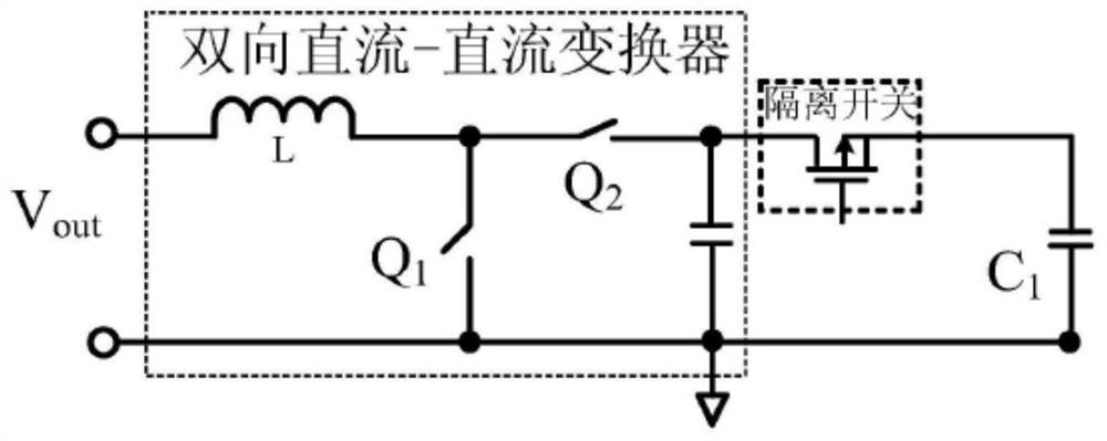
[0033] The main power circuit includes switch K, filter capacitor C L , Energy storage capacitor C H , and connected between the switch K and the energy storage capacitor C H Between the bidirectional DC converter, the output terminal Vo is drawn from the connection point of the switch K and the bidirectional converter, and the input terminal Vin is drawn from the other end of the switch K, and the filter capacitor C L It is connected between the output terminal Vo and the reference ground terminal GND. The bidirectional DC converter includes an inductor L, a switch tube S1, a switch tube S2, a diode D1 and a diode D2. The bidirectional DC converter is controlled by the cont...

no. 2 example

[0060] Please refer to Figure 7 , the power-down holding circuit of the present embodiment is basically the same as that of the first embodiment, both including the main power circuit and the controller; comparison Figure 4 and Figure 7 It can be seen that the main difference between this embodiment and the first embodiment is that the second embodiment changes the switch K at the input end to a controllable switch S3, and other connections and working principles are the same, and will not be repeated here. However, the control method of the holdover circuit in this embodiment is the same as that in the first embodiment.

[0061] Compared with the first embodiment, the advantage of this embodiment is that when it is applied to medium and high power power-failure retention, the use of a controllable switch S3 with a small on-resistance can further reduce losses and improve system efficiency.

[0062] That is to say, when the holdover circuit of the present invention is app...


PUM


Abstract

The invention belongs to the field of switching power supplies, and relates to a power failure holding circuit and a control method. The power failure holding circuit comprises a controller, a switch, a filter capacitor, an energy storage capacitor and a bidirectional direct-current converter, and the bidirectional direct-current converter comprises an inductor, a switching tube S1, a switching tube S2, a diode D1 and a diode D2; the bidirectional direct-current converter is controlled by the controller to enable the power-down holding circuit to work in a boost mode, a buck mode or a free discharge mode. In a boost mode, the inductor, the switching tube S1 and the diode D2 form a boost circuit; in a buck mode, the inductor, the switching tube S2 and the diode D1 form a step-down circuit, and the switching tube S2 works in an on-off state; in the free discharge mode, the switching tube S2 is controlled to be in a normally-on state, and the energy storage capacitor directly supplies power to the output voltage. The boost and buck modes are controlled by independent switching tubes, the switching response speed of the boost and buck modes is high, and the problems of narrow application range, complex control and slow mode switching dynamic response in the prior art can be effectively solved.

Description

technical field [0001] The invention relates to the field of switching power supplies with a power-down holding time requirement, in particular to a power-down holding circuit and a control method. Background technique [0002] DC-DC switching power supply is usually used as a secondary power supply, and it is widely used in many occasions such as electric power, communication, aerospace, and industrial control. In these applications, it is generally required that when the input voltage of the DC-DC switching power supply is interrupted, its output voltage can still be maintained within the specified range for a certain period of time, so that the controller in its load can continue to work normally and record relevant data. This time is the power-down hold time. For example, in the application of railway power supply, the EN50155 standard stipulates the power-down hold time. When it is S1 level, it is required that the power-down hold time of the DC-DC switching power supp...

Claims


Application Information

Patent Timeline
Patent Type & Authority Applications(China)
IPC IPC(8): H02M3/07H02M1/00
CPCH02M3/07H02M1/00
Inventor 不公告发明人
Owner MORNSUN GUANGZHOU SCI & TECH
Why Eureka
Try Eureka