
Disinfection device for livestock farm

A technology of disinfection device and farm, applied in disinfection, spray device, water supply device and other directions to achieve uniform spraying effect

Inactive Publication Date: 2021-12-07
张超 +4
View PDF0 Cites 3 Cited by
  • Summary
  • Abstract
  • Description
  • Claims
  • Application Information

AI Technical Summary

Problems solved by technology

[0004] The object of the present invention is to provide a disinfection device for livestock farms, which has the advantages of reducing the labor intensity and automatically stirring the disinfectant solution, and solves the problem of manual disinfection

Method used


Image

  • Disinfection device for livestock farm
  • Disinfection device for livestock farm
  • Disinfection device for livestock farm

Examples


Embodiment 1

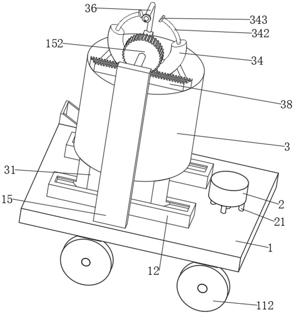
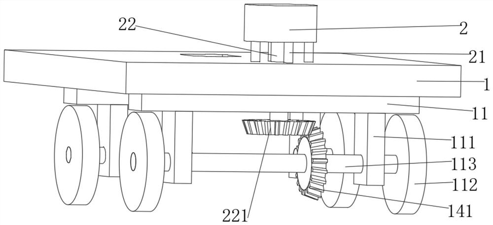
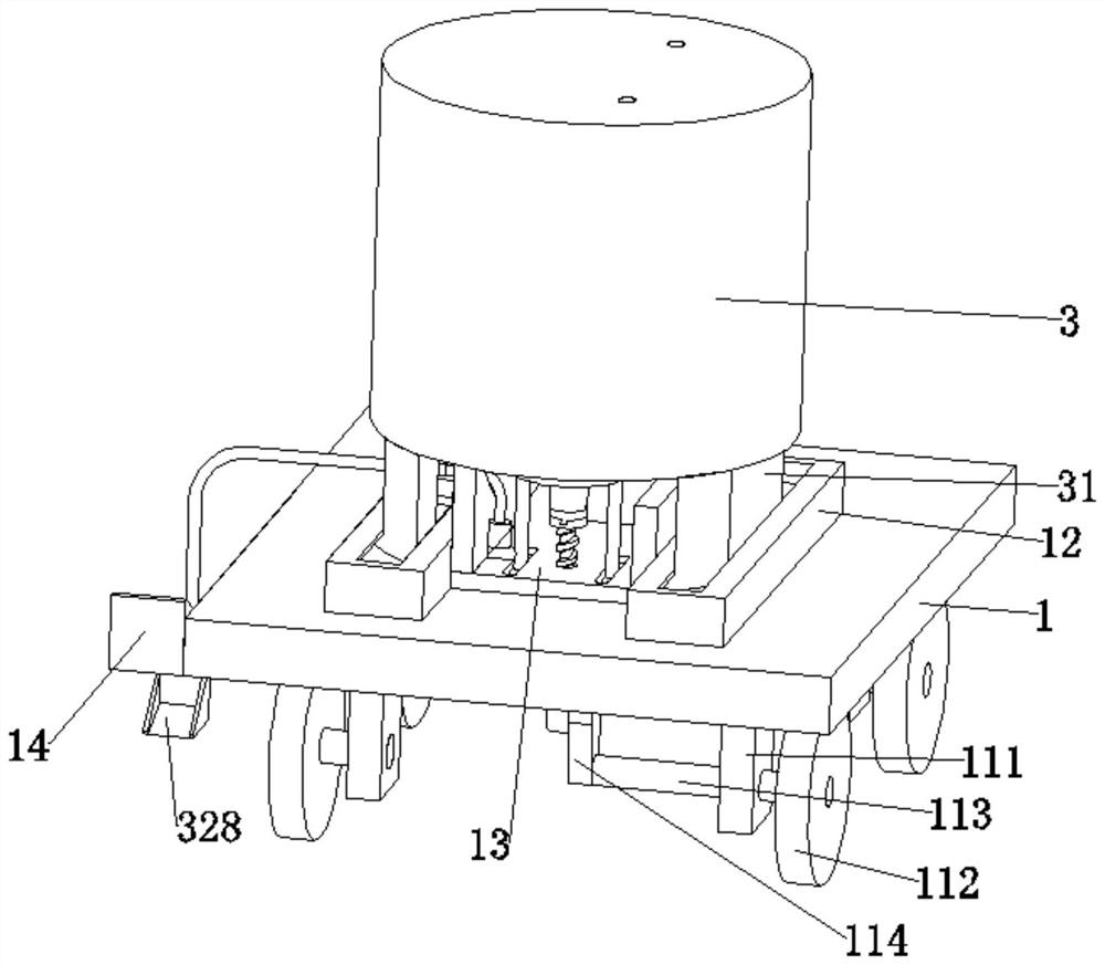
[0032] The present invention provides a technical solution: a disinfection device for animal husbandry farms, including a load-bearing plate 1, a first support plate 12 is fixedly connected to the load-bearing plate 1, a chute is provided on the first support plate 12, and the chute limits A slide rail 31 is slidingly connected, the upper surface of the slide rail 31 is fixedly connected with a housing 3 for placing disinfectant, the load-bearing plate 1 is fixedly connected with a motor frame 21, and the motor frame 21 is fixedly connected with a motor 2, and the output of the motor 2 The end is fixedly connected with a rotating shaft 22 that runs through the bearing plate 1, and the arc profile of the rotating shaft 22 is fixedly connected with a first bevel gear 221. The lower surface of the bearing plate 1 is fixedly connected with a connecting frame 11, and the lower surface of the connecting frame 11 A supporting block 111 is fixedly connected, and a first rotating rod 11...

Embodiment 2

[0047] It is basically the same as Embodiment 1, except that the housing 3 is provided with a spraying mechanism for spraying disinfectant, the spraying mechanism includes a support rod 391 fixedly connected to the upper surface of the housing 3, and the upper surface of the support rod 391 is fixed A water pump 39 is connected, and the lower surface of the water pump 39 is fixedly connected with a second conveying pipe 352. The end of the second conveying pipe 352 away from the water pump 39 runs through the upper surface of the housing 3 and is located under the water surface of the disinfectant. The water pump 39 is fixedly connected with a spraying pipe. Head 36.

[0048] refer to Figure 10 and Figure 11 The effect of supporting the water pump 39 is achieved by setting the support rod 391, the effect of extracting the disinfectant solution from the housing 3 is achieved by setting the second delivery pipe 352 and the water pump 39, and the effect of spraying the extract...


PUM


Abstract

The invention discloses a disinfection device for a livestock farm. The disinfection device comprises a bearing plate, wherein a first supporting plate is fixedly connected to the bearing plate; a sliding chute is formed in the first supporting plate, and a sliding rail is connected to the first supporting plate in a limiting and sliding manner through the sliding chute; a shell for placing a disinfectant is fixedly connected to the upper surface of the sliding rail; a motor frame is fixedly connected to the bearing plate; a motor is fixedly connected to the motor frame; a rotating shaft penetrating through the bearing plate is fixedly connected to the output end of the motor; a first bevel gear is fixedly connected to the arc-shaped contour of the rotating shaft; a connecting frame is fixedly connected to the lower surface of the bearing plate; a supporting block is fixedly connected to the lower surface of the connecting frame; and a first rotating rod is rotationally connected to the supporting block close to one side of the motor. According to the disinfection device disclosed by the invention, due to cooperation of the overall mechanism, the effect of uniformly spraying the disinfectant when the disinfection device moves is achieved; and due to the arrangement of a stirring mechanism, the disinfectant does not precipitate in the shell, so that the optimal effect is achieved during use.

Description

technical field [0001] The invention relates to the technical field of disinfection devices, in particular to a disinfection device for livestock farms. Background technique [0002] Animal husbandry is the use of livestock and poultry and other animals that have been domesticated by humans, or the physiological functions of wild animals such as deer, musk deer, fox, mink, otter, quail, etc., through artificial feeding and breeding, so that they can transform the energy of plants such as pasture and feed The production department of livestock products such as meat, eggs, milk, wool, cashmere, hides, silk and medicinal materials for animals. Different from self-sufficient livestock breeding, the main characteristics of animal husbandry are centralized, large-scale, and profit-oriented production. Animal husbandry is an extremely important link in the material exchange between humans and nature. [0003] At present, in animal husbandry places, in order to keep the ground of ...

Claims


Application Information

Patent Timeline
Patent Type & Authority Applications(China)
IPC IPC(8): A61L2/18A61L2/26B05B15/25B05B3/14A47L11/40
CPCA61L2/18A61L2/26B05B15/25B05B3/14A47L11/4052A47L11/4036A47L11/40A61L2202/15A61L2202/16
Inventor 张超胡彦龙方河山李飞艳李沛
Owner 张超
Learn More