

Uniformly-heated wire drawing equipment for optical fiber processing
Patent Information
- Authority / Receiving Office
- CN · China
- Current Assignee / Owner
- 阜阳市鑫盈田智能设备有限公司
- Publication Date
- 2021-12-07
Smart Images
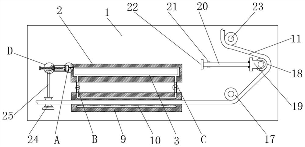
Figure 1 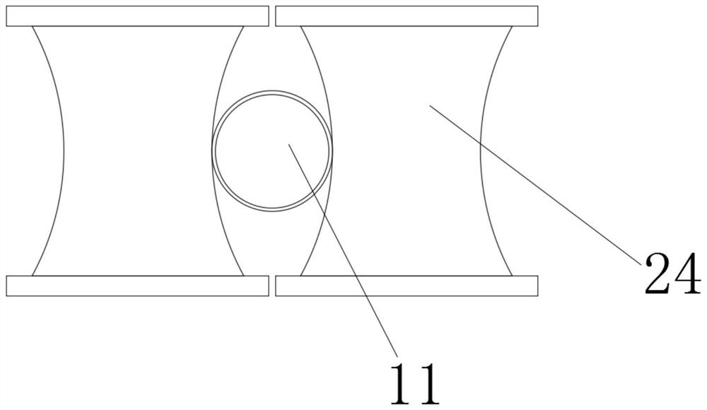
Figure 2 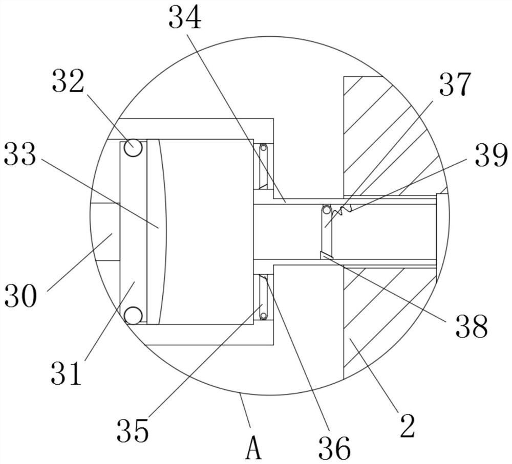
Figure 3
Abstract
Description
technical field
[0001] The invention relates to the technical field of wire drawing equipment, in particular to a wire drawing equipment for optical fiber processing with uniform heating. Background technique
[0002] With the development of modern science and technology, there are more and more applications of optical fibers. When processing optical fibers, the optical fibers are generally calcined, and then pulled out from the annealing furnace for drawing and cooling.
[0003] In order to quickly cool down the drawn optical fiber, the existing method generally uses electrical appliances to continuously cool it down, but this cooling method consumes a lot of energy and has a high cost for long-term use;
[0004] Or use condensate to cool down, but as the optical fiber continues to be pulled, the liquid inside the condensate will gradually increase as the temperature of the absorbed optical fiber rises, so that the cooling effect of the optical fiber in the early stage is b...