Method for hoisting low-clearance super-long reinforcement cage into hole section by section under high-voltage line

A technology of super-long steel cages and steel cages, which is applied in excavation, underwater structures, buildings, etc. It can solve the problems of insufficient rigidity of steel bars connected by hooks, long time-consuming installation of alignment, and high requirements for hoisting technology, so as to achieve convenient and fast Arrangement, avoid lifting instability, high material utilization effect

Pending Publication Date: 2021-12-07
CHINA RAILWAY SHANGHAI ENGINEERING BUREAU GROUP CO LTD
View PDF0 Cites 1 Cited by
  • Summary
  • Abstract
  • Description
  • Claims
  • Application Information

AI Technical Summary

Problems solved by technology

[0002] At present, the excavation of foundation pits of subway stations mostly adopts two types of enclosure structures: ground connection wall and bored piles. Often located in urban areas, there are many buildings and bridges, and there are high-voltage lines above. The line height does not exceed 15m, and construction is not allowed within 6m of the vertical distance of high-voltage lines. Sectional steel cages still have problems such as heavy weight, difficult lifting, and accidents of hoisting instability. Not only is it difficult to locate the position of the steel cage in the pile foundation hole, but it is also easy to cause the steel cage to collide with the hole wall and cause damage to the steel cage. , and the alignment installation takes a long time, and the construction efficiency is low; the steel bar connected by the hook is not rigid enough, and it is easy to deform, and the hoisting process requires high requirements, otherwise it will aggravate the deformation of the steel cage due to the force during hoisting

Method used


Image

  • Method for hoisting low-clearance super-long reinforcement cage into hole section by section under high-voltage line
  • Method for hoisting low-clearance super-long reinforcement cage into hole section by section under high-voltage line
  • Method for hoisting low-clearance super-long reinforcement cage into hole section by section under high-voltage line

Examples


Embodiment Construction

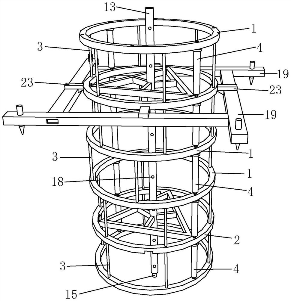
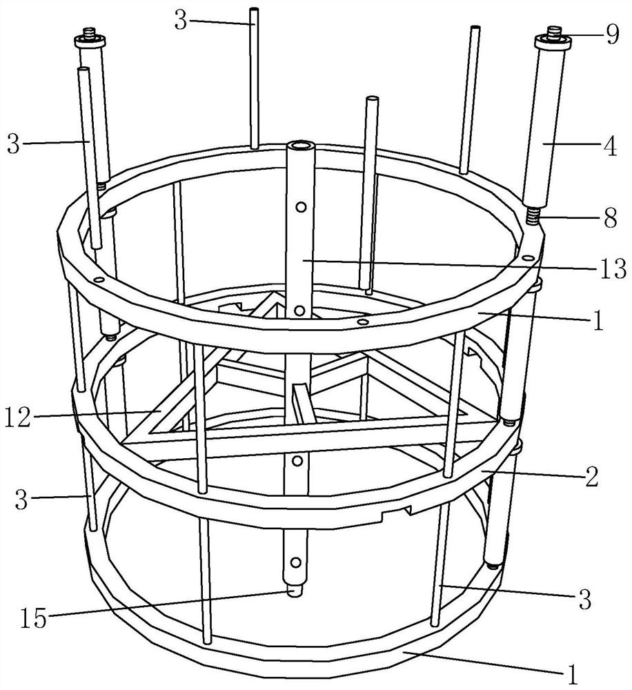
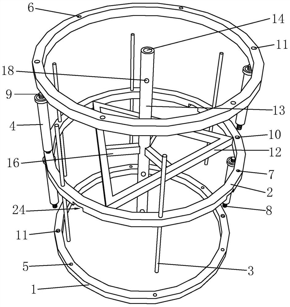
[0043] like Figure 1 to Figure 5 As shown, it is a method for segmentally hoisting a low-clearance super-long reinforcement cage into a hole under a high-voltage line of the present invention, including the following steps:

[0044] (a) Site cleaning: Clean up the garbage around the steel casing, level the ground around the casing, and tamp the soil to provide a good construction environment for the subsequent support brackets and ensure the construction quality of the support brackets.

[0045] (b) Assembling the reinforcement cage: the reinforcement cage consists of a side ring 1, a middle ring 2, a straight steel bar 3 and a connecting rod 4, the middle ring 2 is set between two side rings 1, and the top surface of the side ring 1 is set There is a first positioning concave hole 5 corresponding to the straight steel bar 3, a second positioning concave hole 6 corresponding to the straight steel bar 3 is provided on the bottom surface of the side ring 1, and a second positio...


PUM


Abstract

The invention discloses a method for hoisting a low-clearance super-long reinforcement cage into a hole section by section under a high-voltage line. The method comprises the following steps of (a) cleaning a site; (b) assembling a reinforcement cage; (c) butting two sections of reinforcement cages; (d) positioning; and (e) hoisting section by section. The method for hoisting the reinforcement cage into the hole in a segmented mode is adopted, pile holes of different depths can be flexibly adapted, the enough reinforcement cage burying depth is guaranteed, the problem that construction is not allowed within the vertical distance range of 6 m of the high-voltage line is solved, the construction operation of hoisting the long reinforcement cage into the hole at the limited height is achieved, the hoisting weight of the single-section reinforcement cage is more effectively controlled, the accident of hoisting instability of the whole-section reinforcement cage is avoided, and the safety of constructors and equipment is guaranteed.

Description

technical field [0001] The invention belongs to the technical field of building construction, and in particular relates to a method for segmentally hoisting and loading a low-clearance super-long reinforcement cage into a hole under a high-voltage line. Background technique [0002] At present, the excavation of foundation pits of subway stations mostly adopts two types of enclosure structures: ground connection wall and bored piles. Often located in urban areas, there are many buildings and bridges, and there are high-voltage lines above. Sectional steel cages still have problems such as heavy weight, difficulty in lifting, and accidents of hoisting instability. Not only is it difficult to locate the position of the steel cage in the pile foundation hole, but it is also easy to cause the steel cage to collide with the hole wall and cause damage to the steel cage. , and the alignment installation takes a long time, and the construction efficiency is low; the steel bar conne...

Claims


Application Information

Patent Timeline
Patent Type & Authority Applications(China)
IPC IPC(8): E02D17/04E02D5/34E02D29/045
CPCE02D17/04E02D5/34E02D29/045E02D29/04
Inventor 章郑远刘俊王庆雨陆跃刘国辉王勇刘道清梁剑锋陈华军连金苟张学武居仪新狄少通杨桂平杨明安张北京
Owner CHINA RAILWAY SHANGHAI ENGINEERING BUREAU GROUP CO LTD
Why Eureka
Try Eureka