
Device for removing accumulated water in pothole terrain in building construction

A technology for building construction and potholes, applied in the field of stagnant water cleaning, can solve problems such as difficulty in walking for construction machinery and construction personnel, difficulty in removing stagnant water, affecting construction speed, etc., to improve speed, facilitate walking, and increase water intake Effect

Active Publication Date: 2021-12-07
武传辉
View PDF8 Cites 0 Cited by
  • Summary
  • Abstract
  • Description
  • Claims
  • Application Information

AI Technical Summary

Problems solved by technology

[0005] Aiming at the deficiencies of the prior art, the present invention provides a device for removing accumulated water in construction potholes, which has a fast drainage speed, does not need to pull wires and drainage hoses on the construction site, is convenient for construction machinery and construction personnel to walk, and can drain the pits The accumulated water at the excavation site has the advantages of pumping and draining cleanly, which solves the problem that traditional pumping and drainage equipment needs to pull more wires and drainage hoses at the bottom of the pit, which makes it difficult for construction machinery and construction personnel to walk during construction, which affects the construction speed. The pumping equipment needs to be a certain distance from the ground to ensure that the water inlet will not be blocked by silt, resulting in the problem that it is difficult to clean up the accumulated water in the potholes

Method used


Image

  • Device for removing accumulated water in pothole terrain in building construction
  • Device for removing accumulated water in pothole terrain in building construction
  • Device for removing accumulated water in pothole terrain in building construction

Examples


Embodiment 1

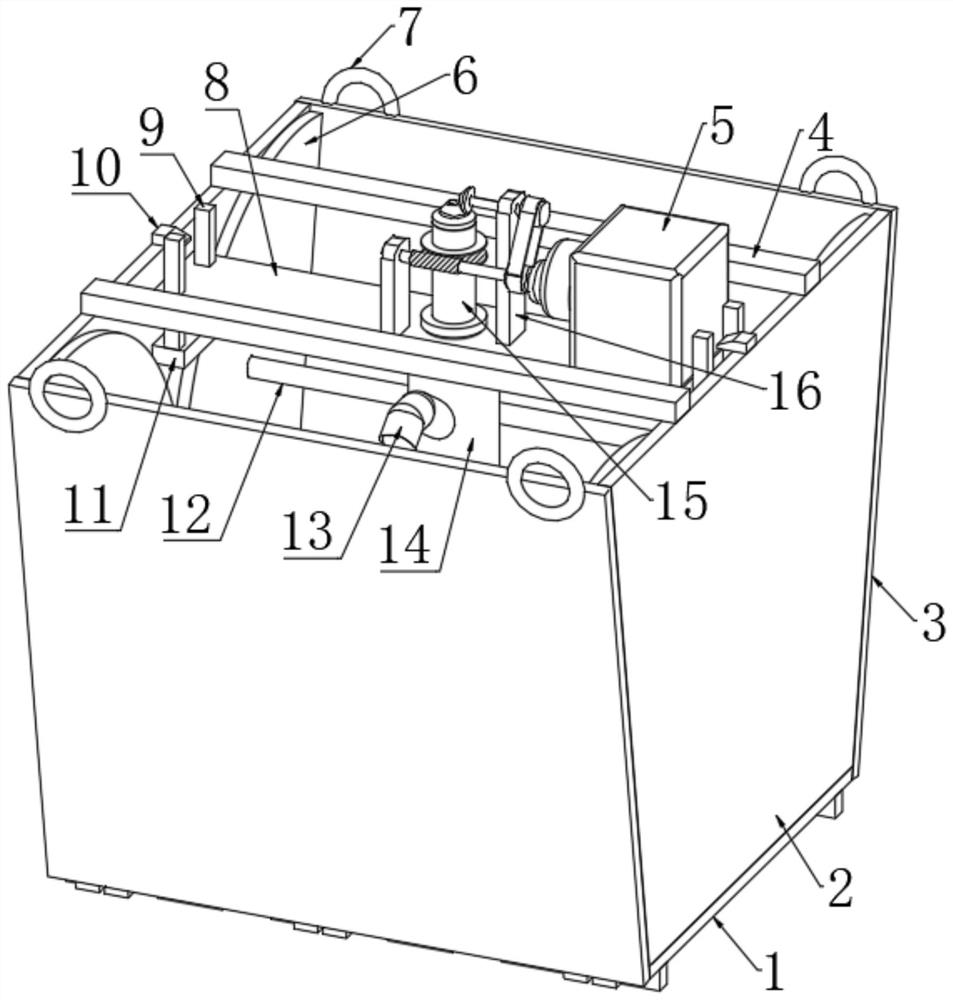
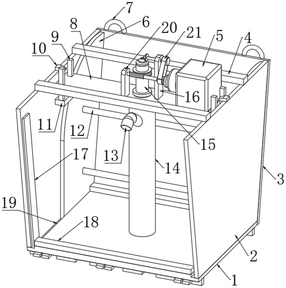
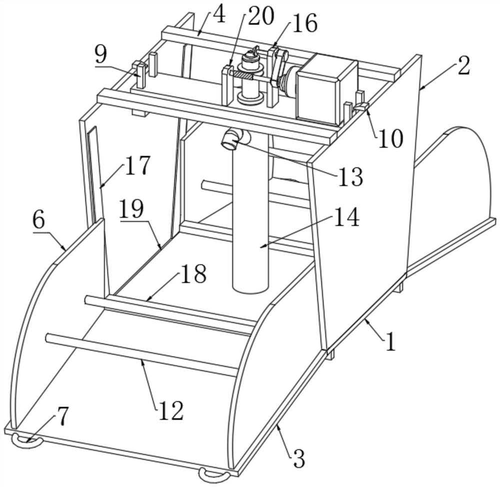
[0028] refer to Figure 1-7, a device for removing accumulated water in construction potholes, comprising a bottom plate 1, the left and right ends of the bottom plate 1 are fixedly connected with trapezoidal plates 2, and the upper ends of the two trapezoidal plates 2 are jointly fixedly connected with two cross bars 4, the bottom plate 1 The center of the upper end of the pipe is fixedly connected with a conduit 14 through a round hole, the upper end of the conduit 14 is provided with a horizontal plate 8, the side wall of the horizontal plate 8 is connected to the tube wall of the conduit 14 through rolling bearings, and the two ends of the horizontal plate 8 are respectively connected with two The opposite side of the trapezoidal plate 2 is connected, one side of the trapezoidal plate 2 is fixedly connected with a rectangular block 11, and the upper end of the rectangular block 11 is fixedly connected with two rectangular rods 9, and the side wall of the horizontal plate 8 ...

Embodiment 2

[0030] Embodiment 2: the difference based on Embodiment 1 is;

[0031] refer to Figure 2-6 , the pumping mechanism includes a rotating shaft 31, the shaft wall of the rotating shaft 31 is rotatably connected with a sealing plate through a sealed bearing, the sealing plate is fixedly connected with the upper end of the casing 15, the shaft wall of the rotating shaft 31 is fixedly connected with a water pump impeller 32, and the upper end of the rotating shaft 31 The first bevel gear 22 passes through the sealed bearing and is fixedly connected. One side of the first bevel gear 22 is meshed with a second bevel gear 23. The upper end of the horizontal plate 8 is fixedly connected with a support rod 16. The rod wall of the support rod 16 passes through the second bevel gear. A ball bearing is rotatably connected with a transmission shaft 24, one end of the transmission shaft 24 is fixedly connected with one side of the second bevel gear 23, the other end of the transmission shaft...

Embodiment 3

[0033] Embodiment 3: the difference based on embodiment 1 is;

[0034] refer to Figure 5-6 , the anti-blocking mechanism includes a plurality of curved rods 33, and the plurality of curved rods 33 are annularly distributed. A transmission rod 34 is fixedly connected, and the rod wall of the transmission rod 34 is fixedly connected with a plurality of uniformly distributed cutter grains 35 through inclined holes, and the lower end of the rotating shaft 31 extends to the outside of the casing 15 and is connected with a circular plate through the second ball bearing. 30, the edge of the circular plate 30 is fixedly connected with one end of the transmission rod 34, the outer edge of the upper end of the casing 15 is fixedly connected with a worm wheel 26, one side of the worm wheel 26 is engaged with a worm 27, and one end of the worm 27 is connected to the second One side of the belt pulley 38 is fixedly connected to the center of the shaft, and one end of the worm 27 is rotat...


PUM


Abstract

The invention relates to the technical field of accumulated water cleaning, and discloses a device for removing accumulated water in a pothole terrain in building construction. The device comprises a bottom plate, wherein trapezoidal plates are fixedly connected to the left end and the right end of the bottom plate, two transverse rods are jointly and fixedly connected to the upper ends of the two trapezoidal plates, a guide pipe is fixedly connected to the center of the upper end of the bottom plate through a round hole, a transverse plate is arranged at the upper end of the guide pipe, the side wall of the transverse plate is rotatably connected with the pipe wall of the guide pipe through a rolling bearing, two ends of the transverse plate are connected with the opposite sides of the two trapezoidal plates respectively, a sleeve is sleeved with the guide pipe, drainage holes are formed in the pipe wall of the sleeve, and rubber rings are fixedly connected to the inner edges of pipe openings of the upper end and the lower end of the guide pipe. According to the device for removing accumulated water in the pothole terrain in building construction, water can be conveniently and rapidly taken from the pothole terrain, water can be pumped after the water is taken, the accumulated water removing speed is further increased, an electric wire and a drainage hose do not need to be pulled on a construction site, and meanwhile, accumulated water at a pit digging position can be pumped and drained thoroughly.

Description

technical field [0001] The invention relates to the technical field of accumulated water cleaning, in particular to a device for removing accumulated water in construction potholes. Background technique [0002] The foundation pit for building construction is an earth pit excavated at the foundation design position according to the base elevation and foundation plane size. Before excavation, the excavation plan should be determined according to the geological and hydrological data, combined with the conditions of the buildings near the site, and waterproof and drainage should be done. If the excavation is not deep, the side slope can be used to stabilize the soil slope. The slope size is determined according to the relevant construction engineering regulations. If the excavation is deep and there are buildings nearby, the foundation pit wall support method can be used, and the sprayed concrete Wall protection method, large-scale foundation pit even adopts methods such as und...

Claims


Application Information

Patent Timeline
Patent Type & Authority Applications(China)
IPC IPC(8): E03F5/22E02D19/02E02D19/10
CPCE03F5/22E02D19/02E02D19/10
Inventor 武传辉
Owner 武传辉
Learn More