
Bypass system optimization method for solving unsmooth drainage of deep peak regulation operation heater

A technology of poor drainage and peak-shaving operation, which is applied in the direction of machines/engines, safety devices, mechanical equipment, etc., can solve problems such as large resistance along the way, unreasonable pipeline layout, and improper selection of drainage regulating valves, etc., to achieve improved Efficiency, improving the effect of safe and economical operation

Pending Publication Date: 2021-12-07
XIAN THERMAL POWER RES INST CO LTD +1
View PDF6 Cites 0 Cited by
  • Summary
  • Abstract
  • Description
  • Claims
  • Application Information

AI Technical Summary

Problems solved by technology

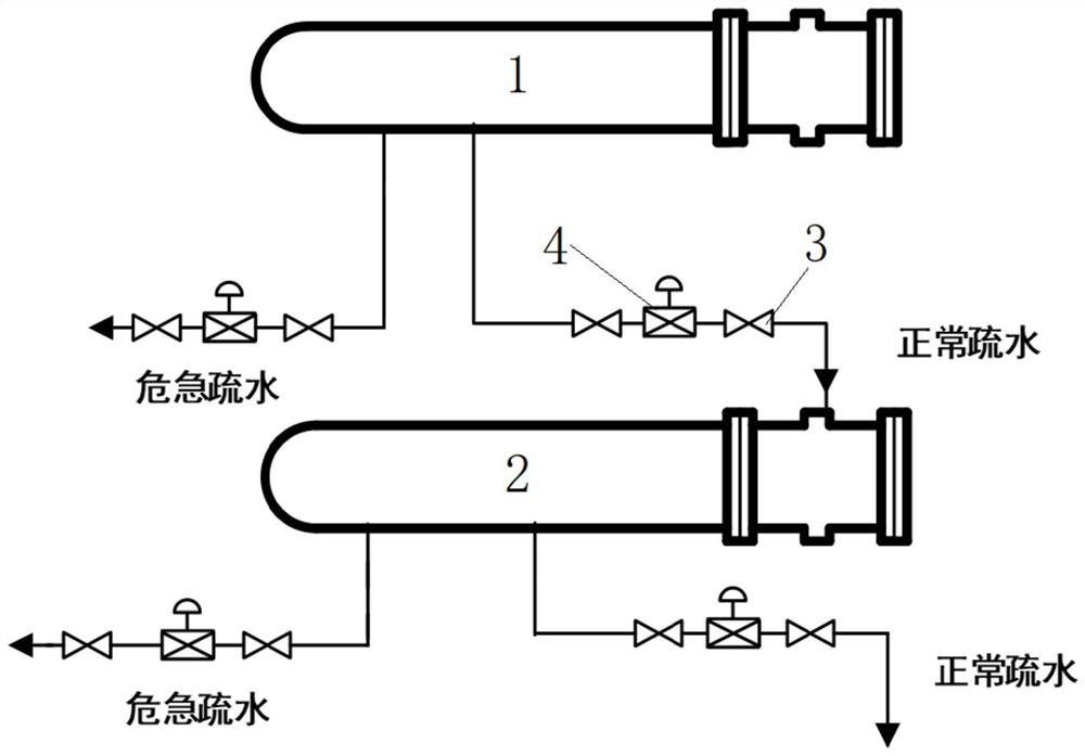
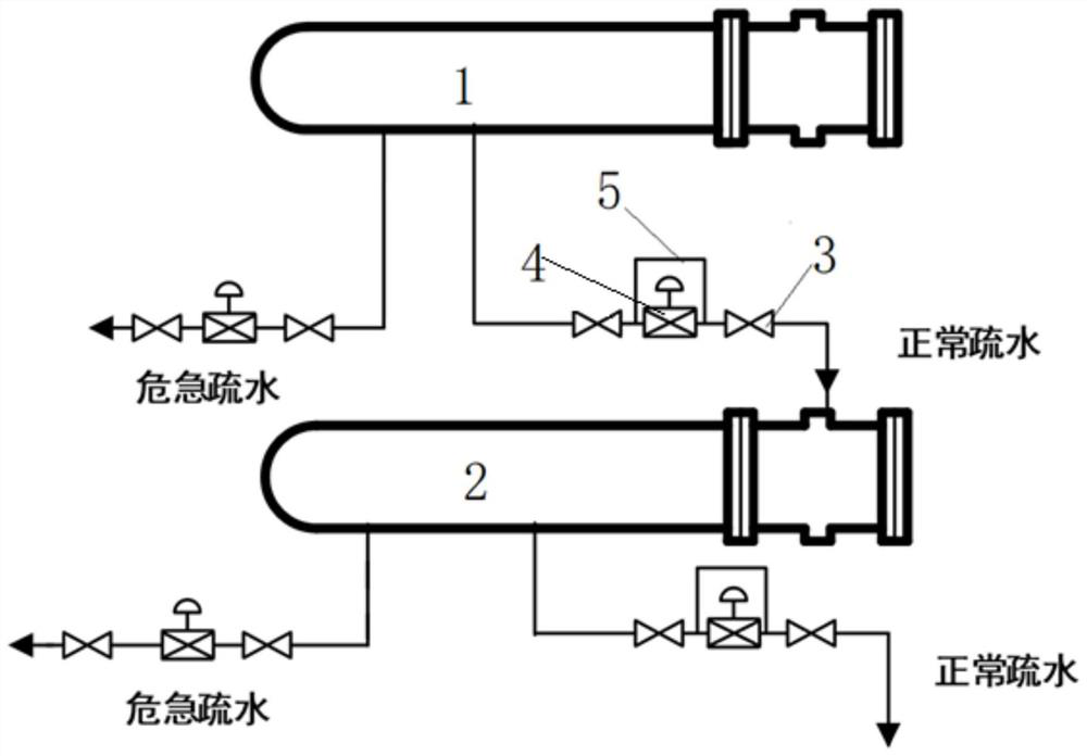
[0004] The purpose of the present invention is to overcome the above-mentioned deficiencies, and provide a bypass system optimization method to solve the problem of poor water drainage of the heater in deep peak-shaving operation, which can optimize the existing heater water drainage system of the unit. A small-diameter bypass pipeline is added to the pipeline system to solve the problem of large resistance along the way caused by improper selection of the drain regulating valve or unreasonable pipeline layout, and avoid opening of the critical drain valve during low-load operation. High-quality The working fluid is directly poured into the condenser, thereby reducing loss of efficiency

Method used


Image

  • Bypass system optimization method for solving unsmooth drainage of deep peak regulation operation heater
  • Bypass system optimization method for solving unsmooth drainage of deep peak regulation operation heater
  • Bypass system optimization method for solving unsmooth drainage of deep peak regulation operation heater

Examples


Embodiment Construction

[0068] The present invention will be further described below in conjunction with the accompanying drawings.

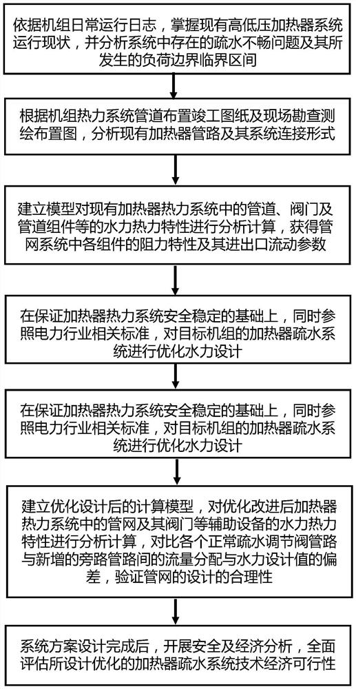
[0069] see figure 1 , the present invention comprises the following steps:

[0070] The present invention comprises the following steps:

[0071] S1, according to the operation log of the unit, obtain the operation status of the heater system, and analyze the load boundary critical interval that occurs when the heater system has poor drainage;

[0072] The operation log of the unit includes the design data of the heater, the current set value of the water level of the heater, the maintenance record of the heater, the content of the maintenance and the emergency repair record, the performance index of the heater under the current rated load condition, the operation log of the unit, the heater occurrence The load boundary with poor drainage and the historical operation data of the steam turbine extraction system and heater system in this state, and the design data incl...


PUM


Abstract

The invention discloses a bypass system optimization method for solving the unsmooth drainage of a deep peak regulation operation heater. The method comprises the following steps that a unit operation log is collected and analyzed, the current operation situation of a current heater system and a load boundary critical interval of the unsmooth drainage of the heater system are mastered, the optimization result is calculated according to the hydraulic and thermal characteristics in the heater system, bypass pipelines are additionally arranged at a drain regulating valve pipeline system of the heater system, finally, the drift diameters of the bypass pipelines are adjusted according to the deviation between flow distribution between each drain regulating valve pipeline and the bypass pipelines and a hydraulic design value, and optimization design is completed. According to the bypass system optimization method, the problem that on-way resistance is large due to improper type selection of the drain regulating valves or unreasonable pipeline arrangement is solved, and the situation that the drain regulating valves are opened urgently during low-load operation is avoided; and a high-quality working medium is directly poured into a condenser, so that the purposes of reducing loss and improving unit efficiency are achieved, and the method is of great significance to improvement of safe and economical operation of a unit.

Description

technical field [0001] The invention belongs to the field of thermal power generation, and in particular relates to a bypass system optimization method for solving the problem of poor drainage of heaters in deep peak-shaving operation. Background technique [0002] In recent years, with the rapid growth of installed capacity of wind power and photovoltaic power generation, due to its randomness, intermittency, instability and other characteristics, a large proportion of access has a greater impact on the stability of the power grid. Compared with the United States, Europe and other countries and regions, my country has fewer gas-fired generating units, and the power supply for rapid load changes to stabilize power grid fluctuations is insufficient. Thermal power units have to undertake the task of power grid peak regulation. Therefore, in order to improve the ability of the power grid to accommodate renewable energy power generation, thermal power units need to undergo furth...

Claims


Application Information

Patent Timeline
Patent Type & Authority Applications(China)
IPC IPC(8): F01D25/32F01D25/30F01D25/10F01D21/00
CPCF01D25/32F01D25/30F01D21/003F01D25/10
Inventor 高庆朱蓬勃屈杰马汀山居文平张京华杨宁辉
Owner XIAN THERMAL POWER RES INST CO LTD
Learn More