Shell-and-tube heat exchanger with refrigerant distribution device

A shell-and-tube heat exchanger and refrigerant distribution technology, which is applied in the direction of heat exchanger shell, indirect heat exchanger, heat exchanger type, etc., can solve the problems of low working efficiency of shell-and-tube heat exchanger and achieve material saving cost, reduce dosage, enhance the effect of uniformity

Active Publication Date: 2021-12-07
江苏世林博尔制冷设备有限公司
View PDF5 Cites 1 Cited by
  • Summary
  • Abstract
  • Description
  • Claims
  • Application Information

AI Technical Summary

Problems solved by technology

[0003] The purpose of the present invention is to solve the problem of low working efficiency of the existing shell-and-tube heat exchanger, and propose a shell-and-tube heat exchanger with a refrigerant distribution device, which can save the length of the heat exchange tube and greatly improve the work efficiency of the heat exchanger. efficiency

Method used


Image

  • Shell-and-tube heat exchanger with refrigerant distribution device
  • Shell-and-tube heat exchanger with refrigerant distribution device
  • Shell-and-tube heat exchanger with refrigerant distribution device

Examples


Embodiment Construction

[0029] The present invention will be further described below in conjunction with the accompanying drawings.

[0030] The present invention is illustrated by taking the four-system heat exchanger as an example. The upper and lower parts of the two sides of the four-system structure are respectively provided with two sets of independent refrigerant inlets and outlets, and share the water side for heat exchange. It should be understood that the specific embodiments described here are only used to explain the present invention, not to limit it.

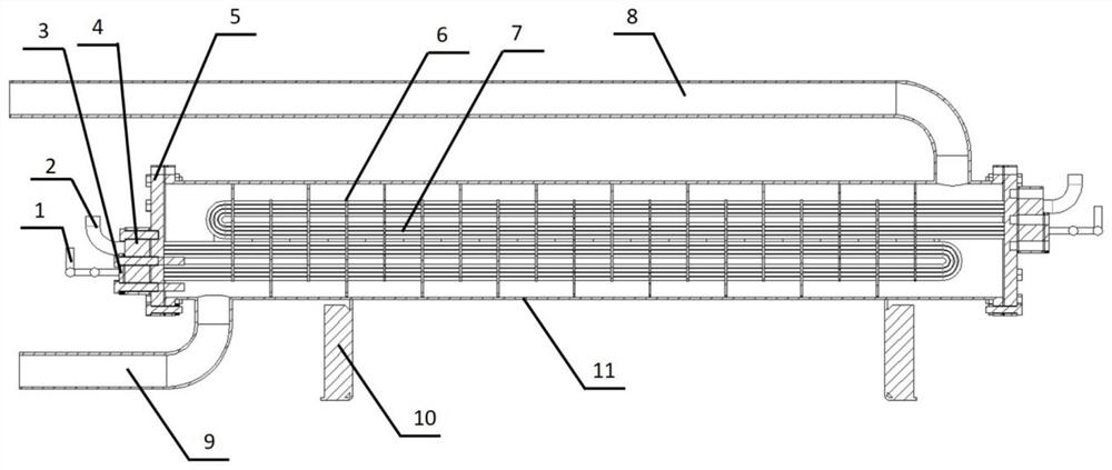
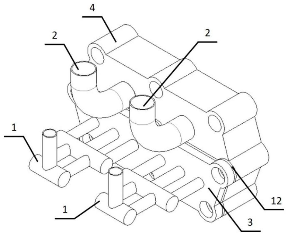
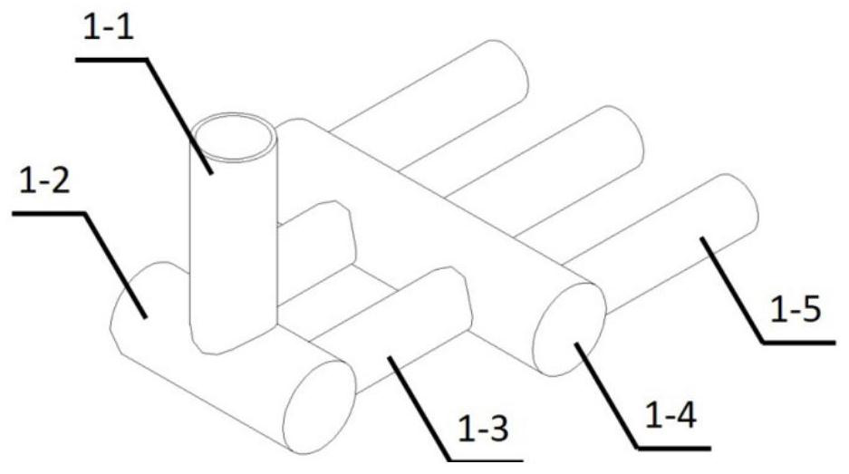
[0031] see Figure 1-Figure 5 , a shell-and-tube heat exchanger with a refrigerant distribution device, including a refrigerant distribution pipe 1, a refrigerant outlet pipe 2, a cover plate 3, an end cap 4, a tube plate 5, an arcuate baffle plate 6, a heat exchange tube 7, water Side outlet pipe 8 , water side inlet pipe 9 , bracket 10 and cylinder 11 . Among them, there are several bow-shaped baffles 6; one end of the cylinder 11 is ...


PUM


Abstract

The invention discloses a shell-and-tube heat exchanger with a refrigerant distribution device. The shell-and-tube heat exchanger with the refrigerant distribution device comprises a refrigerant outlet pipe, a distribution structure, a tube plate and a barrel. A tube plate is arranged at one end of the barrel; a heat exchange tube and a plurality of segmental baffles are arranged in the barrel; the distribution structure is arranged at a refrigerant inlet at one end of the barrel and comprises a refrigerant distribution tube, a cover plate and an end cover; the refrigerant distribution tube is connected with the cover plate; the cover plate is connected with the end cover; and the end cover is connected with the tube plate. The refrigerant distribution pipe comprises a first-stage distribution pipe, a first-stage transverse pipe, a second-stage distribution pipe, a second-stage transverse pipe and a third-stage distribution pipe; the first-stage distribution pipe communicates with the first-stage transverse pipe; the first-stage transverse pipe communicates with the second-stage distribution pipe; the second-stage distribution pipe communicates with the second-stage transverse pipe; and the second-stage transverse pipe communicates with the third-stage distribution pipe. The shell-and-tube heat exchanger with the refrigerant distribution device has the advantages that the whole size of the shell-and-tube heat exchanger is close to that of an existing product, the matching degree with a system is high, and replacement is convenient. By arranging the inlet distribution structure and the segmental baffles, the amount of heat exchange tubes is reduced by more than 30%.

Description

technical field [0001] The invention belongs to the technical field of heat exchangers, and in particular relates to a shell-and-tube heat exchanger with a refrigerant distribution device. Background technique [0002] Shell-and-tube heat exchangers are mainly composed of cylinders, end covers, tube sheets, baffles, heat exchange tubes and other components. Due to their simple structure, strong adaptability, and easy maintenance, they are widely used in many industrial fields. Applications. When the shell-and-tube heat exchanger is used as the central air-conditioning evaporator, the existing structure has the following disadvantages: the uneven distribution of the working medium in each heat-exchanging copper tube leads to different heat transfer required, and the heat transfer efficiency is low; The waste of thermal area increases the cost; the sealing is difficult and easy to leak; the processing is complicated, etc. Contents of the invention [0003] The purpose of t...

Claims


Application Information

Patent Timeline
Patent Type & Authority Applications(China)
IPC IPC(8): F25B39/02F28D7/06F28F9/02F28F9/24F28F11/02
CPCF25B39/028F28D7/06F28F9/24F28F9/0275F28F11/02F25B2339/0242
Inventor 李明杰袁博魏进家吴风雷叶剑波洪建军张涛
Owner 江苏世林博尔制冷设备有限公司
Why Eureka
Try Eureka