
Control method for safe combustion of industrial furnace

A control method and technology for industrial furnaces, which are applied in combustion methods, furnace control devices, and combustion control to achieve the effect of avoiding explosions and other safety accidents and reducing safety risks.

Pending Publication Date: 2021-12-07
SINOPEC ENG +1
View PDF0 Cites 1 Cited by
  • Summary
  • Abstract
  • Description
  • Claims
  • Application Information

AI Technical Summary

Problems solved by technology

[0004] Therefore, the existing industrial furnace combustion control methods are difficult to further meet the requirements of energy saving and safe operation

Method used


Image

  • Control method for safe combustion of industrial furnace

Examples


Embodiment

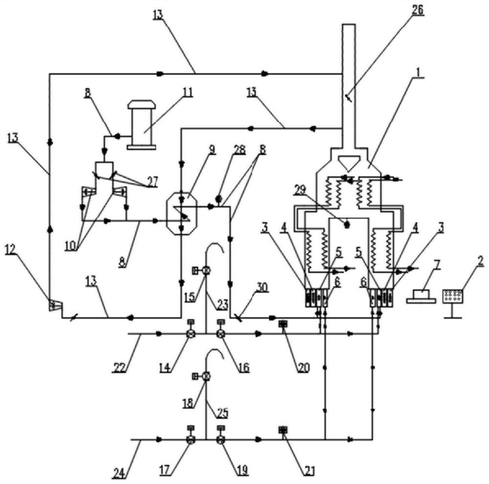
[0051] figure 1 The shown industrial furnace includes industrial furnace body 1, main burner fuel pipeline 22, pilot lamp fuel pipeline 24, combustion air duct 8, pilot lamp 6 and main burner 5; the volume of the furnace is 2050m 3 , take the following steps to carry out safe ignition and operation control of the industrial furnace:

[0052] S1: Leak detection of fuel lines

[0053] Through the sequential pressurization and pressure release of the main burner fuel pipeline 22 and the pilot lamp fuel pipeline 24, at the same time cooperate with the main flame fuel gas regulating valve 14, the main flame fuel gas vent valve 15 the main flame fuel gas cut-off valve 16 the pilot lamp fuel gas regulating valve 17 The switch of the fuel gas vent valve 18 and the fuel gas cut-off valve 19 of the permanent lamp. By comparing the pressure difference of the main flame fuel gas pressure measuring instrument 20 and the pilot light fuel gas pressure measuring instrument 21 before and aft...


PUM


Abstract

The invention relates to a control method for safe combustion of an industrial furnace. According to the control method, the operation of the next link is carried out on the premise that the safety of the previous link is ensured in the ignition and operation process of the industrial furnace, the safety risk in the ignition and operation process of the industrial furnace is reduced to the maximum extent through real-time monitoring and adjustment of all the links in the process, explosions and other safety accidents caused by misoperation or equipment faults are avoided, and the industrial furnace can be located in a safe, efficient and stable operation state.

Description

technical field [0001] The present disclosure relates to the field of safety control of industrial furnaces, in particular, to a method for controlling safe combustion of industrial furnaces. Background technique [0002] Industrial furnaces are the key equipment for providing heat in the refining and chemical process. In recent years, as the country has increasingly higher requirements for refining and chemical enterprises in terms of safety, efficiency, and environmental protection, the combustion monitoring and control level of industrial furnaces has been comprehensively improved. , to ensure the safe production of refining and chemical enterprises, and to achieve energy saving and consumption reduction have become the development goals of the petrochemical industry. [0003] Once unburned substances within the explosion limit range come into contact with an open flame, they will burn and explode. As an open flame equipment in the petrochemical industry, industrial furn...

Claims


Application Information

Patent Timeline
Patent Type & Authority Applications(China)
IPC IPC(8): F27D19/00F27D21/00F23N1/02
CPCF27D19/00F27D21/00F23N1/022F27D2019/004F23N2229/00F23N2231/06
Inventor 王曦宏张伟乾罗亮蔡建光孙毅艾国王志民韩健
Owner SINOPEC ENG
Learn More