
Rope system type manual excitation control system and control method thereof

A control system and vibration excitation technology, which is applied in vibration testing, machine/structural component testing, measuring devices, etc., can solve the problems of structural dynamic characteristics, high operating costs, and large size, so as to improve efficiency and reduce manpower and material resources Cost, effect of improving accuracy

Pending Publication Date: 2021-12-07
GUANGZHOU UNIVERSITY
View PDF10 Cites 2 Cited by
  • Summary
  • Abstract
  • Description
  • Claims
  • Application Information

AI Technical Summary

Problems solved by technology

[0004] In the existing artificial vibration technology for structures, the vibration device needs to be directly installed on the structure to be vibrated, which makes it impossible to carry out the vibration excitation of many actual engineering structures
This is because, usually, the object structures that need to be artificially excited are often complex structures with the characteristics of high towers and long spans. Large-scale vibration excitation equipment is used. Due to its heavy weight and bulky size, large-scale vibration excitation equipment not only cannot be installed in these specific vibration excitation positions, but the operation cost is high, and it will also affect the dynamic characteristics of the structure itself, making artificial vibration test The result is distorted

Method used


Image

  • Rope system type manual excitation control system and control method thereof
  • Rope system type manual excitation control system and control method thereof
  • Rope system type manual excitation control system and control method thereof

Examples


Embodiment Construction

[0042] The present invention will be further described in detail below in conjunction with the accompanying drawings and specific embodiments. For the step numbers in the following embodiments, it is only set for the convenience of illustration and description, and the order between the steps is not limited in any way. The execution order of each step in the embodiments can be adapted according to the understanding of those skilled in the art sexual adjustment.

[0043] In the description of the present invention, multiple means more than two. If the first and second are described only for the purpose of distinguishing technical features, it cannot be understood as indicating or implying relative importance or implicitly indicating what is indicated The number of technical features or implicitly indicates the order of the indicated technical features. Also, unless defined otherwise, all technical and scientific terms used herein have the same meaning as commonly understood by...


PUM


Abstract

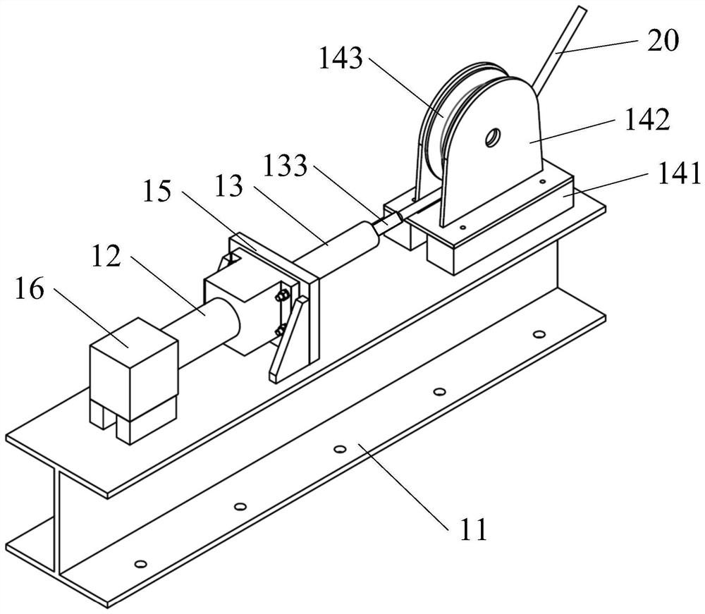
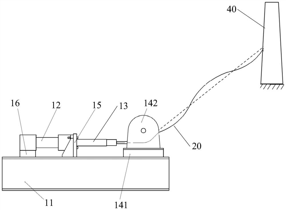
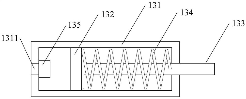
The invention discloses a rope system type manual excitation control system and a control method thereof. The system comprises an actuating device, the actuating device comprises a base, a hydraulic oil cylinder, a servo actuating cylinder and a guide wheel, the hydraulic oil cylinder, the servo actuating cylinder and the guide wheel are all installed on the base, the hydraulic oil cylinder is communicated with an oil path through a high-pressure oil pipe and the servo actuating cylinder, and the hydraulic oil cylinder is used for generating oil path flow; the system further comprises an inhaul cable, one end of the inhaul cable penetrates through the guide wheel to be connected with the piston rod of the servo actuating cylinder, and the other end of the inhaul cable is used for being connected with a vibration excitation object structure; and the system further comprises a controller which is in signal connection with the servo actuating cylinder, and the controller is used for performing hydraulic actuating control on the servo actuating cylinder through the voltage signal. According to the invention, there is no need to install a vibration exciter on the vibration excitation object structure, the accuracy of a vibration excitation test result is improved, the vibration excitation control of a high-altitude and high-rise vibration excitation object structure can be realized in a long distance, the manpower and material resource cost is reduced, the vibration test efficiency is improved, and the system can be widely applied to the technical field of manual vibration excitation.

Description

technical field [0001] The invention relates to the technical field of artificial vibration, in particular to a tethered artificial vibration control system and a control method thereof. Background technique [0002] With the development of building technology and structural engineering and the popularization and application of new materials, new building structures are emerging. These new building structures usually have complex structures, towering, high and soft, or large spans, light weight, or small damping ratio. and other characteristics, some even exceed the design codes and standards, and become over-limit structures, which are prone to vibration responses under the action of wind, earthquake, crowd activities, or traffic vibration, which affect the comfort and function of the structure, and even endanger the structure. Structural safety cannot be ignored. [0003] In order to evaluate the service performance of the structure and ensure the comfort, function and sa...

Claims


Application Information

Patent Timeline
Patent Type & Authority Applications(China)
IPC IPC(8): G01M7/02
CPCG01M7/022
Inventor 陈洋洋周福霖刘彦辉徐丽周惠蒙张颖陈建秋黄襄云马玉宏刘海
Owner GUANGZHOU UNIVERSITY
Learn More