
Wafer edge exposure device and method and photoetching equipment

An edge exposure and wafer technology, which is applied in the direction of microlithography exposure equipment, photolithography exposure equipment, photomechanical equipment, etc., can solve the problems of exposure, effective grain damage, and lower process yield, so as to improve product quality. rate, damage avoidance

Pending Publication Date: 2021-12-07
CHANGXIN MEMORY TECH INC
View PDF11 Cites 0 Cited by
  • Summary
  • Abstract
  • Description
  • Claims
  • Application Information

AI Technical Summary

Problems solved by technology

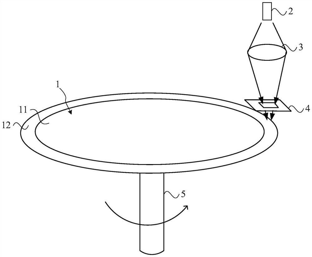
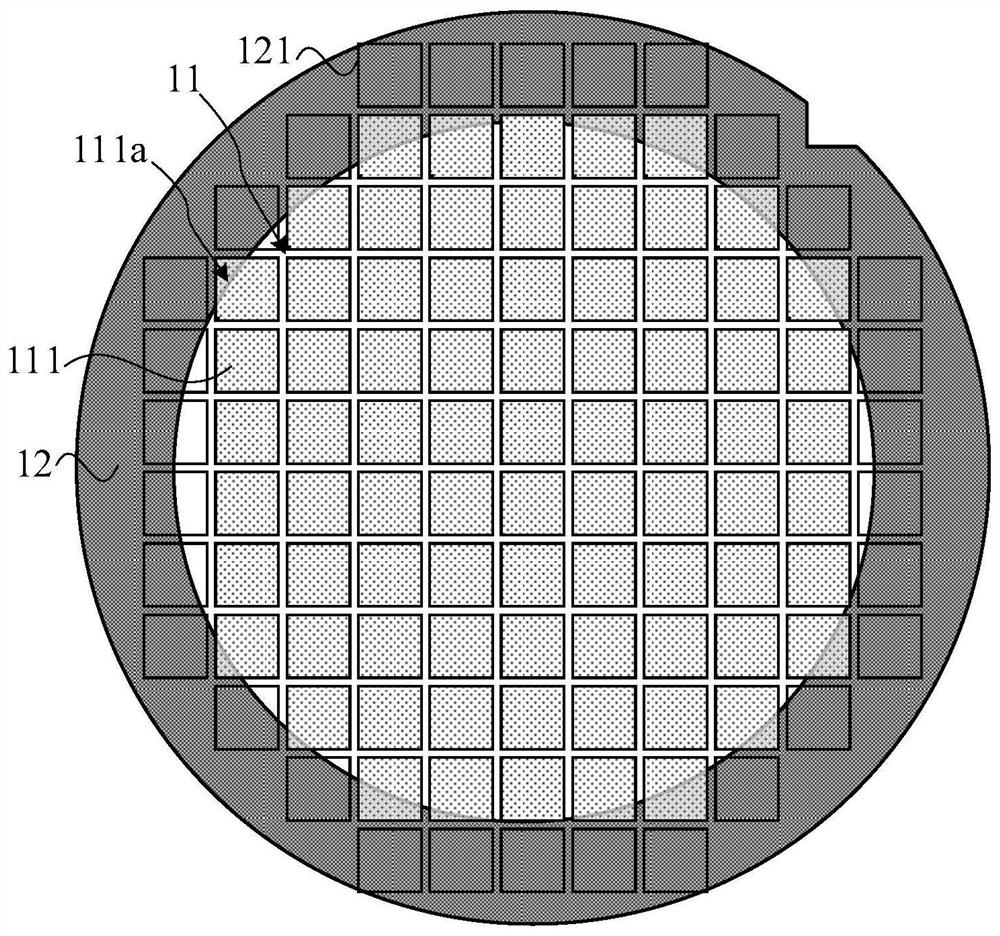
[0004] Compared with the chemical method, although the position and width of the removed crystal edge can be controlled more accurately by the optical method, the existing edge exposure pattern is a concentric ring, which will cause the crystal grains in the effective area to be partially exposed during exposure. Causes effective die damage and reduces process yield

Method used


Image

  • Wafer edge exposure device and method and photoetching equipment
  • Wafer edge exposure device and method and photoetching equipment
  • Wafer edge exposure device and method and photoetching equipment

Examples


Embodiment Construction

[0045] The present invention will be further described in detail below in conjunction with the accompanying drawings and embodiments. It should be understood that the specific embodiments described here are only used to explain the present invention, but not to limit the present invention. In addition, it should be noted that, for the convenience of description, only some structures related to the present invention are shown in the drawings but not all structures.

[0046]Terms used in the embodiments of the present invention are only for the purpose of describing specific embodiments, and are not intended to limit the present invention. It should be noted that the orientation words such as "up", "down", "left", and "right" described in the embodiments of the present invention are described from the angles shown in the drawings, and should not be interpreted as a reference to the implementation of the present invention. Example limitations. Also in this context, it also need...


PUM


Abstract

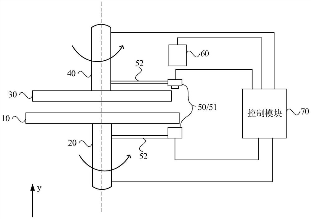
The embodiment of the invention discloses a wafer edge exposure device and method and photoetching equipment. The device comprises a wafer bearing module, a mask plate, a mask plate driving module, an alignment module, an exposure module and a control module; the wafer bearing module is used for bearing a wafer and driving the wafer to rotate; the wafer comprises an effective area and an edge area surrounding the effective area, and the edge area comprises at least one notch unit; the shape of the mask plate is the same as that of the effective area; the mask driving module is used for driving the mask to rotate; the alignment module is used for detecting the alignment state of the mask and the wafer; and the control module is used for controlling the motion states of the wafer bearing module and the mask plate driving module, and is also used for controlling the exposure module to carry out wafer edge exposure on the wafer when the alignment module detects that the mask plate and the wafer are aligned. According to the technical scheme provided by the embodiment of the invention, the damage to the effective area of the wafer can be avoided during wafer edge exposure, and the product yield is improved.

Description

technical field [0001] The invention relates to the technical field of semiconductor manufacturing, in particular to a wafer edge exposure device, method and photolithography equipment. Background technique [0002] With the development of integrated circuits, the density of transistors increases and the critical dimensions shrink, defects generated during the lithography process have an important and directly related impact on device yield and quality, where the cleanliness and definition of wafer boundaries begin to change more important. During the photolithography process, the photoresist is spin-coated on the wafer surface, and there are photoresist accumulations on the upper and lower surfaces near the wafer boundary; during the subsequent etching or ion implantation process, these accumulations are on the wafer boundary The photoresist is likely to collide with the mechanical manipulation arm of the wafer, resulting in particle contamination. Therefore, during the p...

Claims


Application Information

Patent Timeline
IPC IPC(8): G03F1/00G03F7/20H01L21/02
CPCG03F1/00G03F7/70733G03F7/70775G03F7/7085H01L21/02021H01L21/02G03F7/2022Y02P70/50G03F9/7065
Inventor 梁学玉
Owner CHANGXIN MEMORY TECH INC
Learn More