Linear driving equipment

A linear drive and equipment technology, applied in mechanical equipment, transmission devices, electric components, etc., can solve problems such as large gap in motor power requirements, lead accuracy wear, non-parallel guide rails, etc., to save electricity consumption and improve reliability. , the effect of small vibration

Active Publication Date: 2021-12-07
SHENZHEN YAKANGCHENG TECH DEV CO LTD
View PDF18 Cites 1 Cited by
  • Summary
  • Abstract
  • Description
  • Claims
  • Application Information

AI Technical Summary

Problems solved by technology

In the state of vertical movement, an additional balancing device is required. If no balancing device is installed, the linear motor will directly bear the entire weight of the object on the mover, resulting in a huge gap between the upward and downward power requirements of the motor. Once the motor is abnormal or In case of power failure, the mover and the objects on the mover will fall directly, causing stability and reliability problems
[0003] The driving mode of rotary motor plus screw drive, under the same power state, the driving force is several times to tens of times higher than that of linear motor driving mode, which can effectively improve the thrust of the slider; however, it is usually used in An encoder is installed in the motor, and the distance that the slider moves on the shaft is calculated through the angle of rotation of the motor and the lead of the screw. This calculation method requires high accuracy of the lead of the screw. The accuracy of the screw lead cannot meet the requirements, and the precision screw needs to rely on imports; after a long-term use of the precision screw, the lead accuracy will also wear out. Non-parallel, resulting in non-uniform leads of the unworn screw, which affects the displacement accuracy of the linear module

Method used


Image

  • Linear driving equipment
  • Linear driving equipment
  • Linear driving equipment

Examples


Embodiment Construction

[0025] The following will clearly and completely describe the technical solutions in the embodiments of the present invention with reference to the accompanying drawings in the embodiments of the present invention. Obviously, the described embodiments are only part of the embodiments of the present invention, not all of them. Based on the embodiments of the present invention, all other embodiments obtained by persons of ordinary skill in the art without creative efforts fall within the protection scope of the present invention.

[0026] It should be noted that all directional indications (such as up, down, left, right, front, back...) in the embodiments of the present invention are only used to explain the relationship between the components in a certain posture (as shown in the accompanying drawings). Relative positional relationship, movement conditions, etc., if the specific posture changes, the directional indication also changes accordingly.

[0027] In addition, in the p...


PUM


Abstract

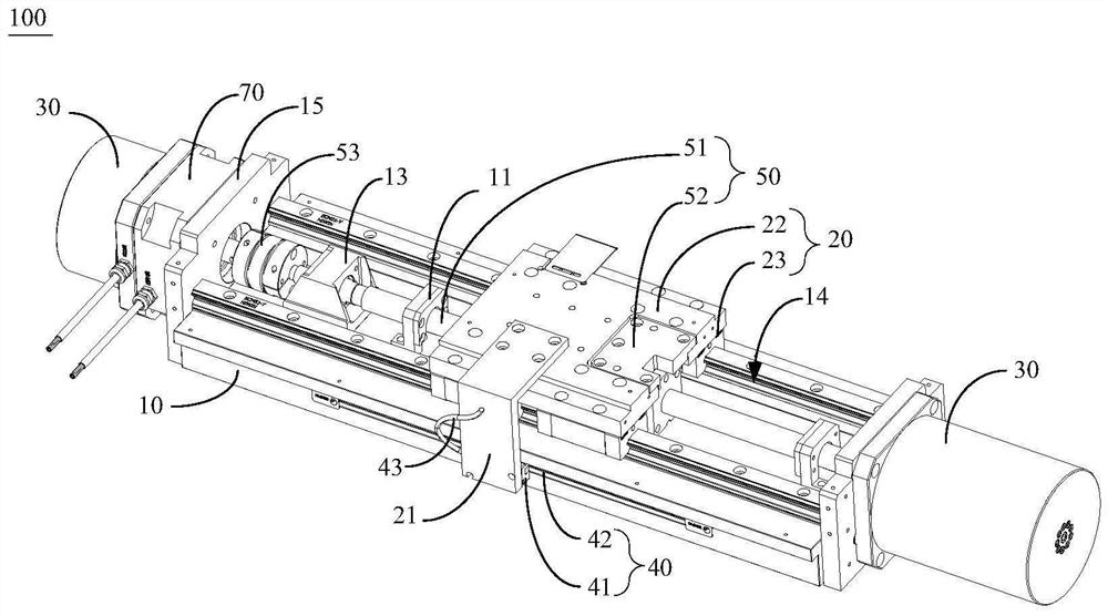
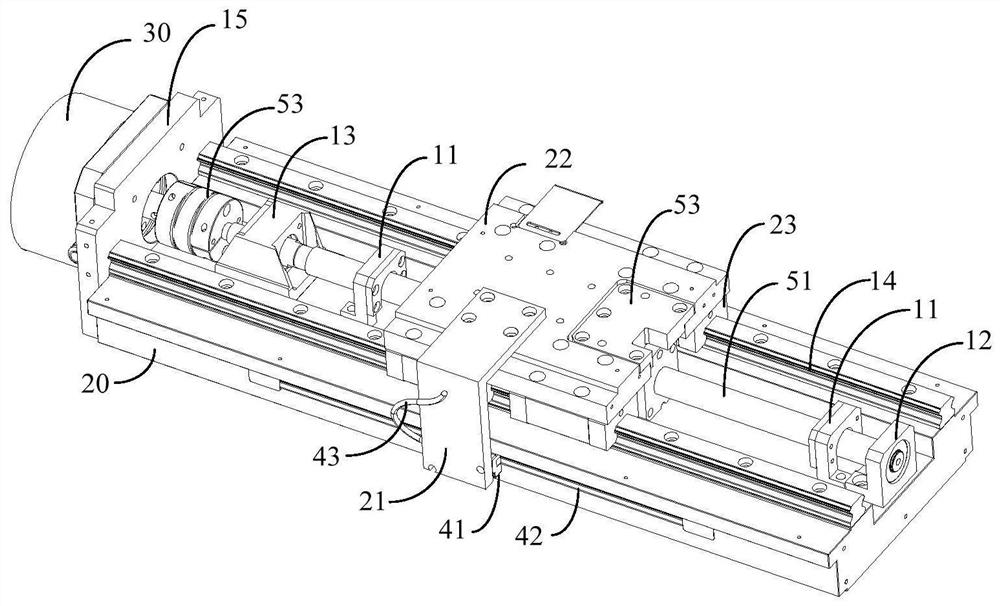
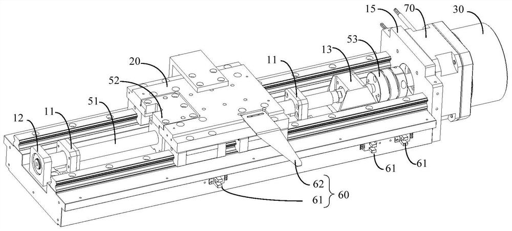
The invention discloses linear driving equipment which comprises a base, a lead screw transmission device, a sliding block, at least one motor and a monitoring device. The lead screw transmission device is arranged on the base; the sliding block is arranged on a nut of the lead screw transmission device; a rotary encoder is not arranged in the motor, and the motor is fixed at one end of the base and is in transmission connection with a lead screw of the lead screw transmission device to drive the lead screw of the lead screw transmission device to rotate, so that the sliding block moves in the length direction of the lead screw; and the monitoring device is a linear position encoder, is arranged between the sliding block and the base to monitor the sliding distance of the sliding block in the length direction of the lead screw, and is electrically connected with a driver of the motor, and starting and stopping of the motor are directly controlled through the driver. According to the technical scheme, on the premise that it is guaranteed that the linear driving equipment has large transmission mechanical force, the control precision of the linear driving equipment is improved, and meanwhile the precision problem caused by lead screw abrasion is solved.

Description

technical field [0001] The invention relates to the technical field of drive devices, in particular to a linear drive device. Background technique [0002] Traditional linear drive equipment includes two types of drive modes: linear motor drive mode, rotary motor plus screw drive drive mode. Among them, the linear motor drive mode directly drives the mover by magnetic force to realize the linear motion of the mover, and then drives the linear displacement of the object fixed on the mover, and the displacement distance is directly fed back to the driver by the linear encoder; High-precision control of the moving distance of the mover. In the state of vertical movement, an additional balancing device is required. If no balancing device is installed, the linear motor will directly bear the entire weight of the object on the mover, resulting in a huge gap between the upward and downward power requirements of the motor. Once the motor is abnormal or In the event of a power fail...

Claims


Application Information

Patent Timeline
Patent Type & Authority Applications(China)
IPC IPC(8): H02K7/06H02K7/10H02K11/21F16H25/20
CPCH02K7/06H02K7/10H02K11/21F16H25/2015F16H25/20F16H2025/2075
Inventor 闫娟
Owner SHENZHEN YAKANGCHENG TECH DEV CO LTD
Why Eureka
Try Eureka