Light component removal rectifying tower

A technology for removing light rectification tower and tower body, applied in the field of rectification tower, can solve the problems of heat transfer oil contact, reduce rectification efficiency, poor separation effect, etc. effect of chance

Pending Publication Date: 2021-12-10
何金翠
View PDF6 Cites 0 Cited by
  • Summary
  • Abstract
  • Description
  • Claims
  • Application Information

AI Technical Summary

Problems solved by technology

[0005] 1. The existing rectification tower cannot make the heat transfer oil evenly contact the liquid phase and the gas phase during the heating process, which will affect the rectification effect. At the same time, when the gas phase and the liquid phase contact, heat exchange will occur due to the temperature difference between the two. Thereby reducing the temperature when the two are in contact, thus reducing the rectification efficiency;
[0006] 2. In addition, during the separation process, the gas molecules of the mixed liquid in rectification will generate a large amount of foam when they pass through the through holes, and the quality of the obtained rectification product will inevitably be affected, making the separation effect poor or even unrealizable.

Method used


Image

  • Light component removal rectifying tower
  • Light component removal rectifying tower
  • Light component removal rectifying tower

Examples


Embodiment Construction

[0031] The following will clearly and completely describe the technical solutions in the embodiments of the present invention with reference to the accompanying drawings in the embodiments of the present invention. Obviously, the described embodiments are only some, not all, embodiments of the present invention. Based on the embodiments of the present invention, all other embodiments obtained by persons of ordinary skill in the art without making creative efforts belong to the protection scope of the present invention.

[0032] see Figure 1 to Figure 5 , the present invention provides a technical solution:

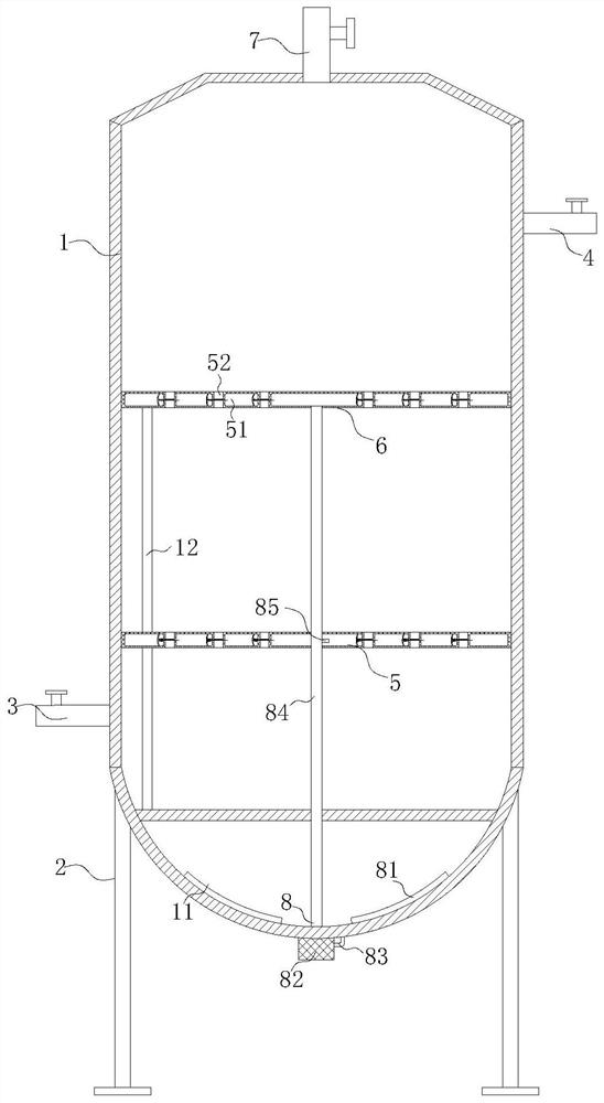
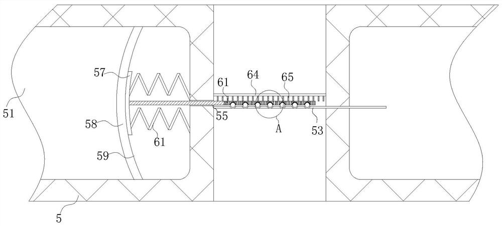
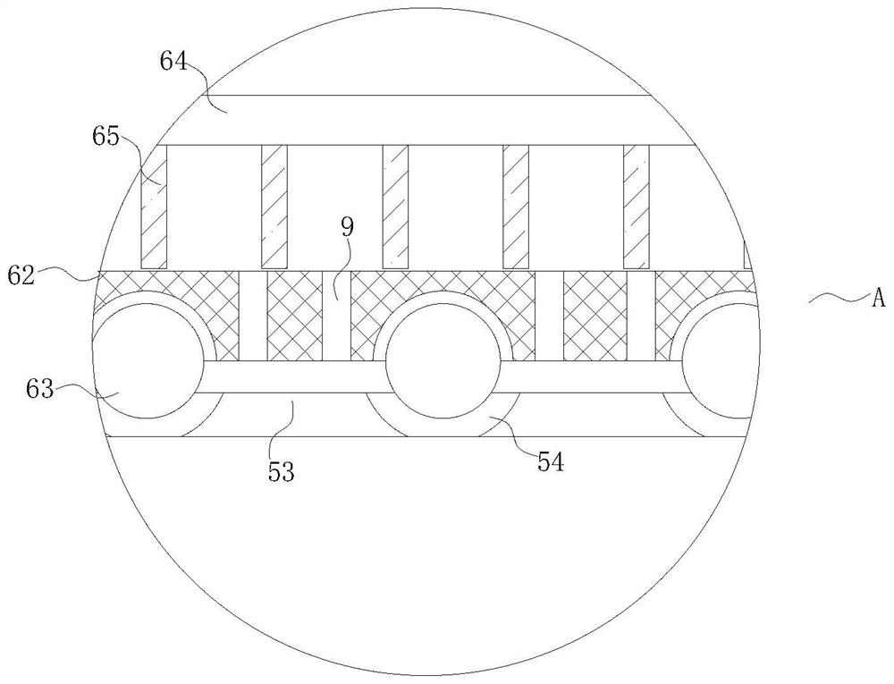
[0033] A lightening distillation column, such as Figure 1 to Figure 4 As shown, it includes a tower body 1, a support frame 2, a gas phase inlet 3, a raw material inlet 4, a packing plate one 5, a packing plate two 6, a gas phase output pipe 7 and a heating assembly 8, and the outer surface of the lower end of the tower body 1 is fixedly connected There is a support fram...


PUM


Abstract

The invention relates to the technical field of rectifying towers, in particular to a light component removal rectifying tower which comprises a tower body, a supporting frame, a gas phase inlet, a raw material inlet, a first filler plate, a second filler plate, a gas phase output pipe and a heating assembly, the supporting frame is fixedly connected to the outer surface of the lower end of the tower body, the position, close to the bottom end, of the outer surface of the left side of the tower body fixedly communicates with the gas phase inlet, the position, close to the upper end, of the outer surface of the right side of the tower body fixedly communicates with a raw material inlet, a first filler plate and a second filler plate are fixedly connected into the tower body, the outer surface of the upper end of the tower body is fixedly connected with a gas phase output pipe, and the heating assembly is arranged in the tower body. By arranging the heating assembly, conduction oil can circularly flow in a heating cavity I and a heating cavity II while the interior of the tower body is heated by utilizing the conduction oil, so that a liquid phase and a gas phase passing through the through holes are heated, the contact temperature of the liquid phase and the gas phase is ensured, the liquid phase and the gas phase are fully rectified, and the rectification efficiency is improved.

Description

technical field [0001] The invention relates to the technical field of rectification towers, in particular to a lightening rectification tower. Background technique [0002] In the chemical industry, it is almost an essential operation to separate various substances with different specific gravity and boiling point. This is usually carried out in a distillation tower or a separation tower (usually a rectification tower), and heat is supplied to the distillation tower through a heating device , output light distillate or low boiling point distillate from the top of the tower, and heavy distillate or high boiling distillate stay in the bottom of the tower and separate from the bottom of the tower. The basic principle of distillation is to partially vaporize the liquid mixture, and use the characteristics of different volatilities of each component in it to realize the unit operation for the purpose of separation. [0003] Existing patent (notification number: CN206867750U) a ...

Claims


Application Information

Patent Timeline
Patent Type & Authority Applications(China)
IPC IPC(8): B01D3/14B01D3/32B01D3/42B01D3/00
CPCB01D3/14B01D3/32B01D3/4211B01D3/009
Inventor 何金翠李庞军
Owner 何金翠
Why Eureka
Try Eureka