Integrated electro-hydraulic braking system device for vehicle

An electro-hydraulic braking and system device technology, applied in the direction of brake transmission, foot start device, brakes, etc. The effect of strong adaptability, saving equipment volume, and solving fault problems

Inactive Publication Date: 2021-12-10
BEIJING YINGCHUANG HUIZHI TECH
View PDF11 Cites 3 Cited by
  • Summary
  • Abstract
  • Description
  • Claims
  • Application Information

AI Technical Summary

Problems solved by technology

Patent CN112061099A adopts the method of connecting redundant solenoid valves in parallel at the decoupling valve of the brake master cylinder and the servo master cylinder and adopts the method of redundant power supply for separate power supply, which can ensure the system when the original solenoid valve part cannot work normally due to power failure and other failures. A certain amount of braking pressure can still be generated to improve vehicle driving safety, but this mechanism complicates the system, and with the further popularization of electrified vehicles, the redundant power supply for backup will further reduce the mileage of the vehicle. Conducive to the transformation of electrification and energy saving in the vehicle industry
[0004] To sum up, in actual use, the decoupling effect of the driver's input force and the motor's input force by the electro-hydraulic brake equipment has high requirements on the working conditions and other conditions, and it is prone to failure, which will cause safety problems. Redundant power supply and redundant power supply are introduced. The structure caused by the electromagnetic valve group becomes complicated and the power consumption increases

Method used


Image

  • Integrated electro-hydraulic braking system device for vehicle

Examples


Embodiment Construction

[0025] The following will clearly and completely describe the technical solutions in the embodiments of the present invention with reference to the accompanying drawings in the embodiments of the present invention. Obviously, the described embodiments are only some, not all, embodiments of the present invention. Based on the embodiments of the present invention, all other embodiments obtained by persons of ordinary skill in the art without making creative efforts belong to the protection scope of the present invention.

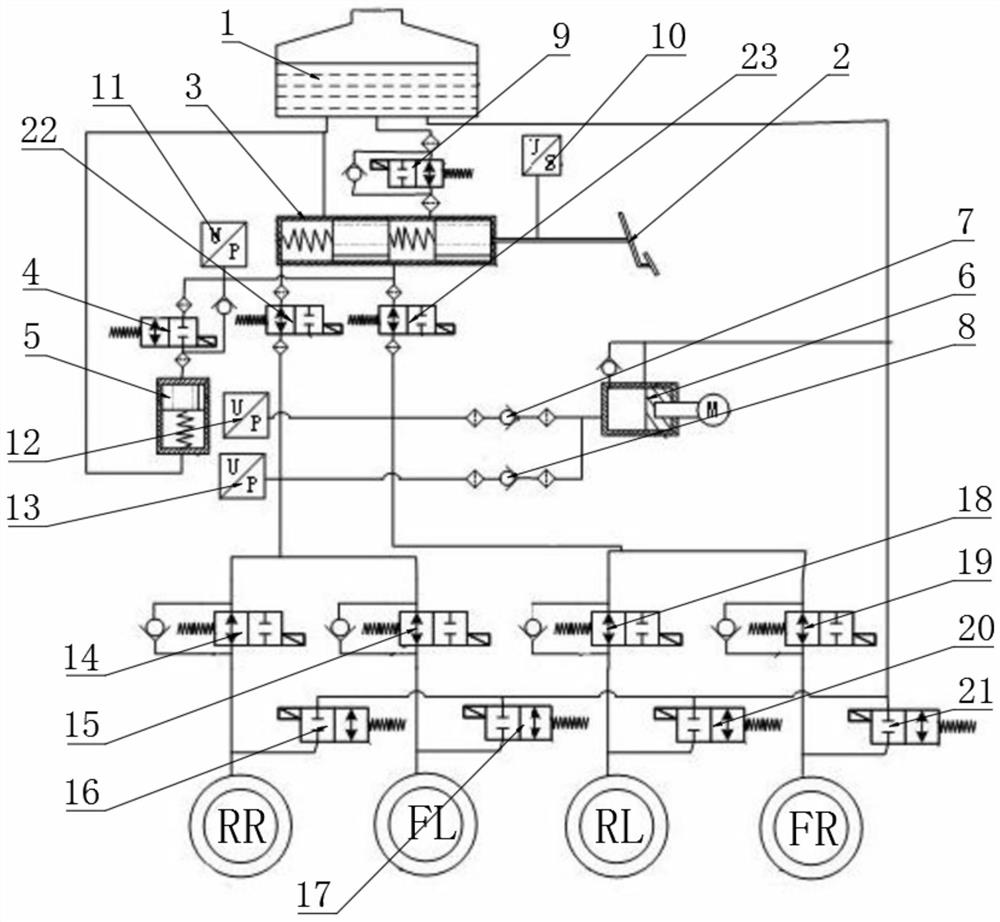
[0026] see figure 1 , the present invention provides a technical solution: comprising:

[0027] Liquid storage tank 1, which is used to store pressurized medium;

[0028] Pedal 2, which is used to operate the brake action;

[0029] Brake master cylinder 3, its piston and pedal 2 operating handle are fixedly installed to provide initial brake pressure, the left chamber liquid inlet and right chamber liquid inlet of brake master cylinder 3 are respectively con...


PUM


Abstract

The invention discloses a vehicle integrated type electro-hydraulic braking system device which comprises a liquid storage tank used for storing a pressurizing fluid; a pedal for operating a braking action; a brake master cylinder, a piston of which is fixedly connected with the pedal operating handle and used for providing initial brake pressure, and a left cavity liquid inlet and a right cavity liquid inlet of the same are connected with an oil inlet and an oil outlet of a liquid storage tank respectively. During conventional braking, a driver steps on the liquid storage tank, and the displacement sensor collects signals and transmits the signals to the ECU; afterwards, the ECU sends instruction signals to all valve modules, a first master cylinder decoupling valve and a second master cylinder decoupling valve are powered on and disconnected, a motor in a servo master cylinder rotates to build pressure in the servo master cylinder, and high-pressure brake fluid is pumped into a wheel cylinder set through a transmission mechanism; due to the fact that the first motor decoupling valve and the second motor decoupling valve are of a one-way valve pure mechanical structure, the adaptability to working conditions is high, and the problem of electromagnetic valve faults is effectively solved.

Description

technical field [0001] The invention relates to the field of electronic hydraulic braking systems, in particular to a vehicle integrated electro-hydraulic braking system device. Background technique [0002] The existing vehicle electronic hydraulic braking system mainly includes a solenoid valve, a pressure sensor, a brake master cylinder, a pedal feeling simulator, a motor, and a servo master cylinder. After the driver steps on the brake pedal, the ECU issues an instruction, the motor builds pressure in the servo master cylinder, and different solenoid valves open or close, so as to realize the decoupling of vehicle driving and the pressure building of the brake wheel cylinder, as shown in the application number CN201811620833.2 provides a hydraulic decoupling electro-hydraulic braking system, which realizes the decoupling of driver input force and motor thrust through two brake master cylinder decoupling valves and two motor decoupling valves, application number CN2020111...

Claims


Application Information

Patent Timeline
Patent Type & Authority Applications(China)
IPC IPC(8): B60T13/68B60T13/14B60T7/06
CPCB60T13/686B60T13/145B60T13/147B60T7/06
Inventor 崔子学刘子俊李晨风
Owner BEIJING YINGCHUANG HUIZHI TECH
Why Eureka
Try Eureka