A quadruped robot for acquiring spatial 3D data
A quadruped robot and three-dimensional data technology, applied in the field of robotics, can solve problems such as decreased precision, waste of kinetic energy, and impact on equipment battery life, and achieve the effect of fast travel and improved grip
- Summary
- Abstract
- Description
- Claims
- Application Information
AI Technical Summary
Problems solved by technology
Method used
Image
Examples
Embodiment 1
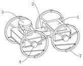
[0032] like figure 1 As shown in the figure, a quadruped robot for obtaining spatial three-dimensional data provided by this embodiment includes a body 1, which is divided into two parts: front and rear, and the middle is hinged by a steering hinge 2 to perform horizontal connection angle rotation, and the front A data collection mechanism 3 is arranged on the side fuselage 1, and the data collection mechanism 3 is hinged with the fuselage 1 to perform angular rotation in a horizontal and vertical plane. A motion mechanism 4 that switches the connection angle between the wheeled state and the bionic foot state.
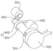
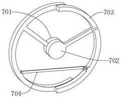
[0033] further, as figure 2 , image 3 As shown, the motion mechanism 4 includes a drive motor, a rotating shaft group 6 and a foot wheel 7, and the four corners of the fuselage 1 are provided with a rotating shaft group 6. The rotating shaft group 6 includes a first rotating shaft 601 and a second rotating shaft 602. The first rotating shaft 601 passes through a b...
Embodiment 2
[0049] The difference between this embodiment and Embodiment 1 is that: Image 6 As shown in the figure, the first arc-shaped member 701 and the second arc-shaped member 703 are incomplete disc-shaped structures, and the disc-shaped structure is provided with through holes arranged in circular arc grooves or arrays that are concentric with the outer edge of the disc. The rod 702 and the second connecting rod 704 are hinged in the grooves or through holes of the first arc-shaped member 701 and the second arc-shaped member 703 through screw assemblies;
[0050] Through the arrangement of the first arc-shaped member 701 and the second arc-shaped member 703 in the disc structure, compared with the ring structure, the structural strength of the first arc-shaped member 701 and the second arc-shaped member 703 is improved, and through the disc structure The grooves or through holes on the surface can instantly adjust the connection positions of the first connecting rod 702, the secon...
Embodiment 3
[0052] The difference between this embodiment and Embodiment 1 is that: Figure 7 As shown, the end of the end of the second arc-shaped member 703 away from the hinge point with the first connecting rod 702 is fixed with an arc-shaped structure bent toward the center side by a screw assembly;
[0053] Through the arrangement of the curved arc structure at the end of the second arc-shaped member 703, when the foot wheel 7 is in the bionic foot shape, the overall angle between the second arc-shaped member 703 and the vertical direction is small, that is, the contact area with the ground is small, which can improve the The contact area between the second arc-shaped member 703 and the ground reduces the pressure at the contact point, that is, when the ground is wet and soft, the contact area between the foot wheel 7 and the ground can be increased by adding an arc structure to prevent the foot wheel 7 from sinking and reducing the The difficulty of robot walking increases the pass...
PUM
 Abstract
Description
Claims
Application Information
 - R&D
- Intellectual Property
- Life Sciences
- Materials
- Tech Scout
- Unparalleled Data Quality
- Higher Quality Content
- 60% Fewer Hallucinations
Browse by: Latest US Patents, China's latest patents, Technical Efficacy Thesaurus, Application Domain, Technology Topic, Popular Technical Reports.
© 2025 PatSnap. All rights reserved.Legal|Privacy policy|Modern Slavery Act Transparency Statement|Sitemap|About US| Contact US: help@patsnap.com


