Textile hair removal equipment with dust collection function based on spinning
A technology for textiles and equipment, applied in the field of textile hair removal equipment, can solve problems such as low efficiency, troublesome cleaning, and fluff falling on the ground.
- Summary
- Abstract
- Description
- Claims
- Application Information
AI Technical Summary
Problems solved by technology
Method used
Image
Examples
Embodiment 1
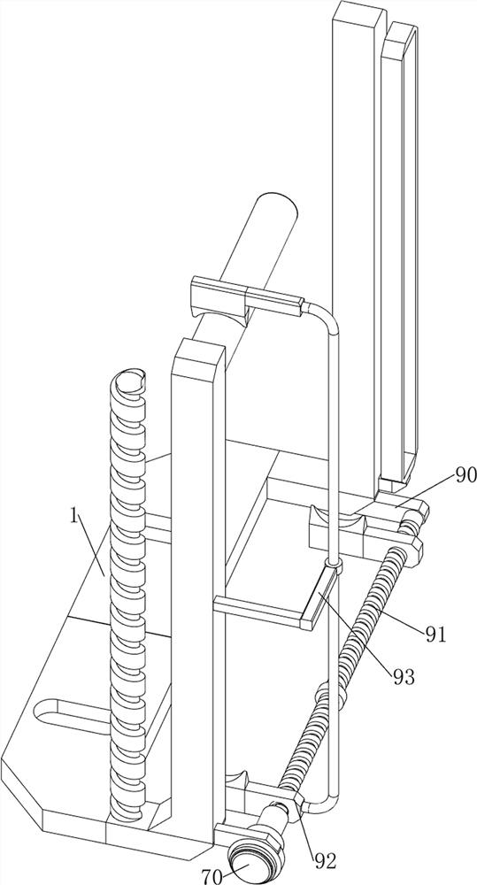
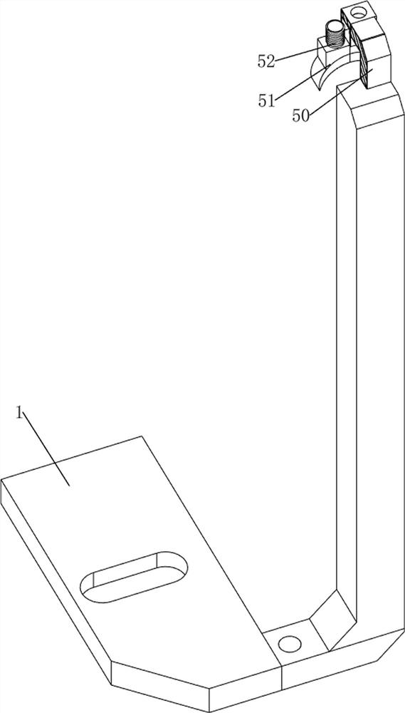
[0057] A kind of textile hair removal equipment with vacuum function based on textile, such as Figure 1-4 As shown, it includes a base plate 1, a first screw mandrel 2, a first movable plate 3, a blade 4, a clamping mechanism 5 and a dust suction mechanism 6. The threaded mandrel 2 is provided with a first movable plate 3, and the left side of the bottom plate 1 is slidably provided with a first movable plate 3, and the two first movable plates 3 correspond to each other, and the first movable plate 3 on both sides is connected with a Two blades 4, a clamping mechanism 5 is provided on the left and right sides of the bottom plate 1, and a dust suction mechanism 6 is provided on the front side of the bottom plate 1.
[0058]When it is necessary to remove hair from textiles, people first pull the clamping mechanism 5 to move upwards, then spread the textiles flat on the bottom plate 1, and no longer apply force to the clamping mechanism 5, under the reset action of the clamping...
Embodiment 2
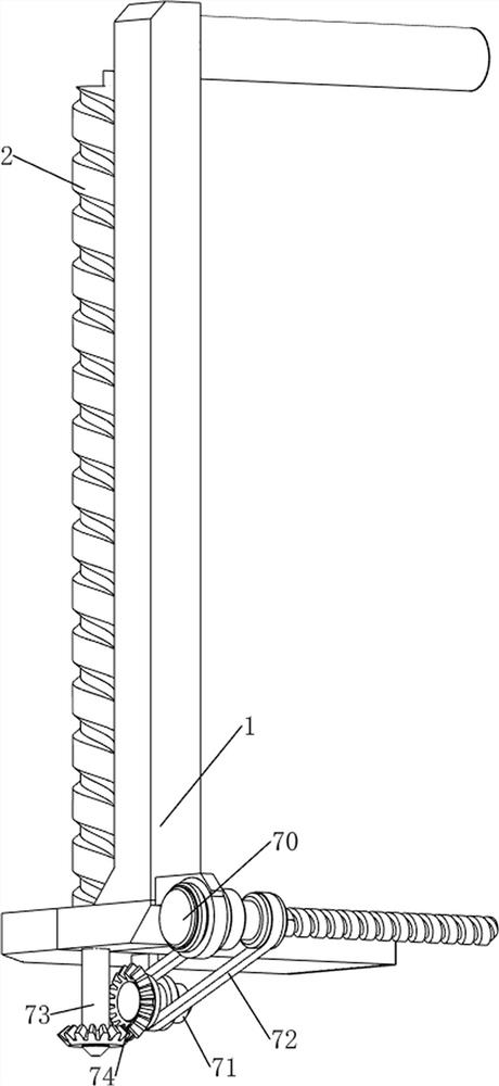
[0064] On the basis of Example 1, such as figure 1 , Figure 5 , Figure 6 , Figure 7 and Figure 8 As shown, a driving mechanism 7 is also included, and the driving mechanism 7 includes a servo motor 70, a first rotating shaft 71, a transmission assembly 72, a second rotating shaft 73 and a bevel gear 74, and the servo motor 70 is installed on the right side of the back of the bottom plate 1, and the bottom of the bottom plate 1 The right side rotation type is provided with a first rotating shaft 71, and a transmission assembly 72 is arranged between the output shaft of the servo motor 70 and the first rotating shaft 71. The transmission assembly 72 is composed of two pulleys and a flat belt, and the two pulleys are respectively connected to the servo motor. 70 on the output shaft and the first rotating shaft 71, the flat belt is wound on the two pulleys, the right side of the base plate 1 is rotatably provided with a second rotating shaft 73, the second rotating shaft 73...
PUM
 Abstract
Description
Claims
Application Information
 - R&D
- Intellectual Property
- Life Sciences
- Materials
- Tech Scout
- Unparalleled Data Quality
- Higher Quality Content
- 60% Fewer Hallucinations
Browse by: Latest US Patents, China's latest patents, Technical Efficacy Thesaurus, Application Domain, Technology Topic, Popular Technical Reports.
© 2025 PatSnap. All rights reserved.Legal|Privacy policy|Modern Slavery Act Transparency Statement|Sitemap|About US| Contact US: help@patsnap.com


