Point-control LED plant growth lamp string
A technology of plant growth lamps and LED light strips, which is applied in the direction of botanical equipment and methods, lampshades, and damage prevention measures for lighting devices, etc., which can solve the problems of not being able to get the light from the lamp beads and not being able to heat the plants, so as to shorten the flowering of plants The time spent on the result, the effect of improving production and rapid heat dissipation
- Summary
- Abstract
- Description
- Claims
- Application Information
AI Technical Summary
Problems solved by technology
Method used
Image
Examples
Embodiment 1
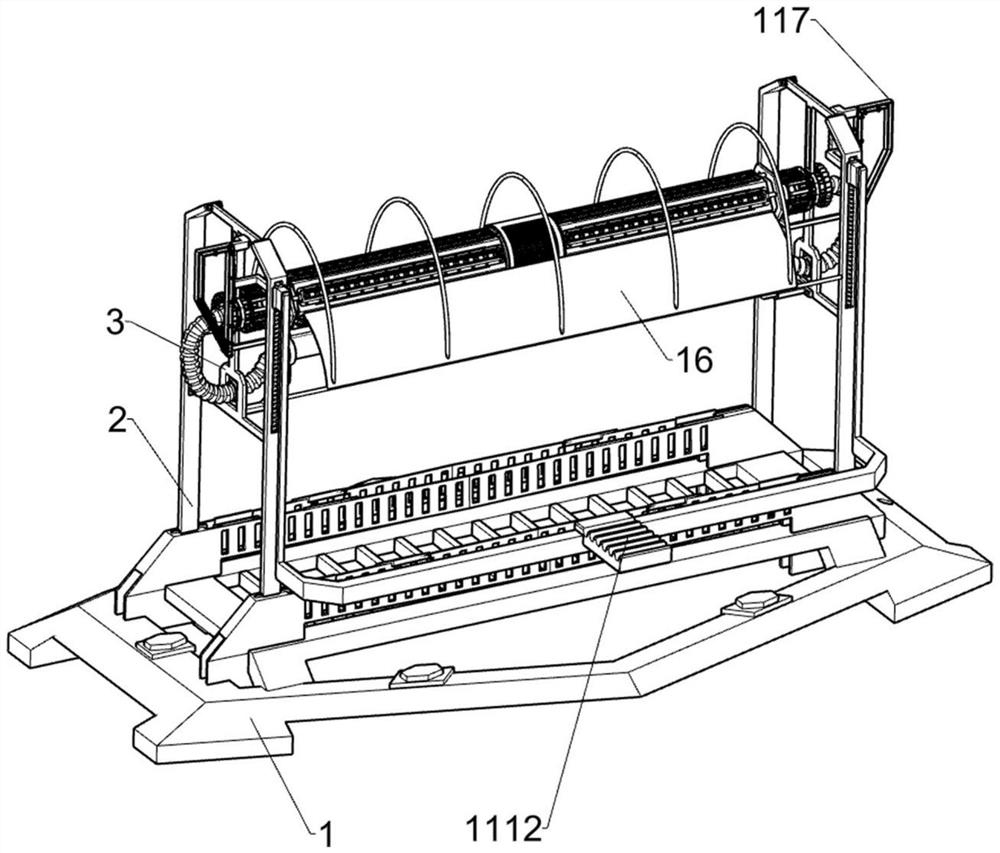
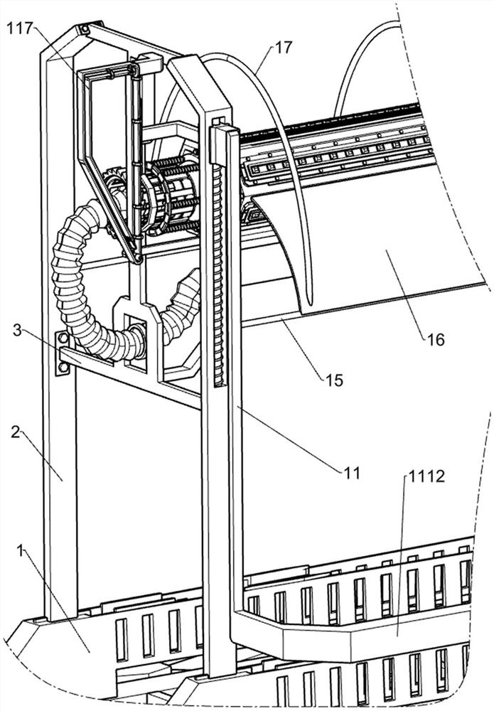
[0046] A point-controlled LED plant growth light string, such as figure 1 , figure 2 , image 3 , Figure 4 , Figure 5 , Figure 6 , Figure 7 , Figure 8 , Figure 11 , Figure 14 , Figure 15 and Figure 16 As shown, it includes base 1, bracket 2, support frame 3, turret 4, Liuling hollow cylinder 5, air intake pipe 6, LED light strip 7, heat dissipation assembly 8 and adjustment assembly 9, and two pairs of Bracket 2, two adjacent brackets 2 are jointly connected with a support frame 3 through a fastener connection mode, a turret 4 is fixedly connected to the support frame 3, and a Liuling hollow cylinder 5 is rotatably connected to the turret 4, and two six The opposite sides of Ling hollow cylinder 5 are fixed together with intake pipe 6 for conveying cold air, and LED light strips 7 are connected to Liuling hollow cylinder 5 in a manner of circumferential distribution, and LED light strips 7 are used to irradiate plants. A heat dissipation assembly 8 for dis...
Embodiment 2
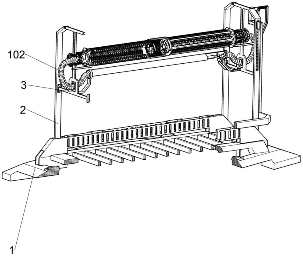
[0052] On the basis of Example 1, such as Figure 6 and Figure 7 As shown, it also includes a heat conduction assembly 10. The Liuling hollow cylinder 5 is provided with a heat conduction assembly 10. The heat conduction assembly 10 is used to guide the hot air and then transfer heat to the plants. The heat conduction assembly 10 includes a conical rotating Cylinder 101, bellows 102, fixed ring block 103, fixed frame 104 and air guide pipe 105, conical rotating cylinder 101 is rotatably connected to Liuling hollow cylinder 5, and bellows for conveying hot air is connected to conical rotating cylinder 101 102, the support frame 3 is fixedly connected with a fixed ring block 103, the bellows 102 runs through the fixed ring block 103, the fixed frame 104 is fixedly connected to one side of the support frame 3, and the two fixed frames 104 are jointly fixed with an air guide tube 105, the air guide tube 105 is used to guide the hot air, and the air duct 105 communicates with the...
Embodiment 3
[0055] On the basis of Example 2, such as Figure 7 , Figure 8 , Figure 9 , Figure 11 and Figure 12 As shown, it also includes a driving assembly 11, wherein the two brackets 2 on one side are jointly provided with a driving assembly 11, and the driving assembly 11 is used to drive the LED light strip 7 to rotate to adjust its position. The driving assembly 11 includes a ratchet 111, Vertical slide block 113, slide bar 114, second spring 115, L-shaped frame 116, ladder frame 117, ratchet frame 118, slide shaft 119, slide plate 1110, the 3rd spring 1111, pedal 1112, ratchet block 1113 and Back-moving spring 1114, one end of Liuling hollow cylinder 5 is fixedly connected with ratchet 111, wherein the two supports 2 on one side are provided with first chute 112, and the first chute 112 is slidably connected with vertical slide block 113, the first slide A slide bar 114 is arranged in the groove 112, and the vertical slide block 113 is slidably connected with the slide bar...
PUM
 Abstract
Description
Claims
Application Information
 - R&D
- Intellectual Property
- Life Sciences
- Materials
- Tech Scout
- Unparalleled Data Quality
- Higher Quality Content
- 60% Fewer Hallucinations
Browse by: Latest US Patents, China's latest patents, Technical Efficacy Thesaurus, Application Domain, Technology Topic, Popular Technical Reports.
© 2025 PatSnap. All rights reserved.Legal|Privacy policy|Modern Slavery Act Transparency Statement|Sitemap|About US| Contact US: help@patsnap.com


