An ultrasonic thickness gauge with couplant recovery function

An ultrasonic and couplant technology, which is applied in the field of ultrasonic thickness gauges with couplant recovery function, can solve the problems of inability to recover couplant at one time, many repetitions of recycling work, and classification and recovery of couplant, etc., so as to improve the detection accuracy. , The effect of reducing the difficulty of processing work and avoiding duplication of work

Active Publication Date: 2022-01-28
胜利油田东强机电设备制造有限公司
View PDF12 Cites 0 Cited by
  • Summary
  • Abstract
  • Description
  • Claims
  • Application Information

AI Technical Summary

Problems solved by technology

[0007] In order to overcome the fact that the existing ultrasonic thickness gauge cannot recover all the couplants at one time, and it is also impossible to classify and recycle the couplants in different states, resulting in repeated recovery times and low efficiency. The coupling of different states obtained by recovery Due to the disadvantages of mixing agents with each other, the present invention provides an ultrasonic thickness gauge with a coupling agent recovery function

Method used


Image

  • An ultrasonic thickness gauge with couplant recovery function
  • An ultrasonic thickness gauge with couplant recovery function
  • An ultrasonic thickness gauge with couplant recovery function

Examples


Embodiment 1

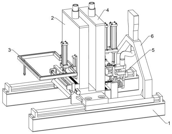
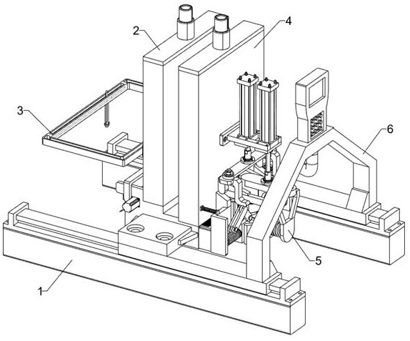
[0042] An ultrasonic thickness gauge with a couplant recovery function, such as Figure 1-2 As shown, it includes propulsion support system 1, pollution layer recovery system 2, middle layer recovery system 4 and ultrasonic thickness measurement system 6. The pollution layer recovery system 2 is installed on the propulsion support system 1, and the right side of the pollution layer recovery system 2 is connected to the middle layer The recovery system 4 is connected with an ultrasonic thickness measurement system 6 on the right side of the middle layer recovery system 4 , and the bottom of the ultrasonic thickness measurement system 6 is fixedly connected with the propulsion support system 1 .

[0043] When using the ultrasonic thickness gauge with the function of couplant recovery, the operator first applies a thick layer of couplant on the object to be measured, and places the object to be measured in the middle of the propulsion support system 1 to control the propulsion sup...

Embodiment 2

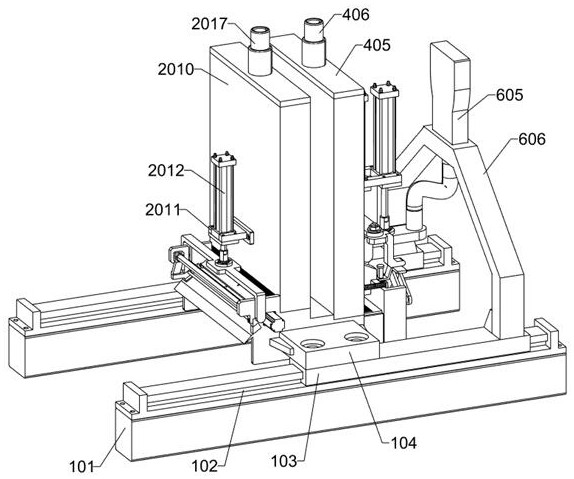
[0045] On the basis of Example 1, such as Figure 3-6 As shown, the propulsion support system 1 includes a support plate 101, a first electric slide rail 102, a first electric slide block 103 and a first connecting plate 104, and each bolt on the upper side of the two support plates 101 is connected with a first electric slide rail 102 , a first electric slider 103 is slidably connected to each of the two first electric slide rails 102 , and a first connecting plate 104 is bolted to each upper side of the two first electric sliders 103 .

[0046] The pollution layer recovery system 2 includes a support frame 201, a motor 202, a pressing plate 203, a first fixing plate 204, a connecting rod 205, a pushing frame 206, a pushing rod 207, a first fixing block 208, and a second fixing block 209 , the first material storage box 2010, the third fixed frame 2011, the first cylinder 2012, the fourth fixed frame 2013, the electric rotating shaft 2014, the pressing rod 2015, the first fil...

Embodiment 3

[0049] On the basis of Example 2, such as Figure 7-11 As shown, the middle recovery system 4 includes a second fixed plate 401, a first baffle 402, a second baffle 403, a second filter 404, a second storage box 405, a second nozzle 406, and a sixth fixed frame 407, the second cylinder 408, the second connecting plate 409, the first connecting frame 4010, the connecting piece 4011, the first elastic member 4012, the first limit rod 4013, the third connecting plate 4014, the fourth connecting plate 4015, the fifth Connecting plate 4016, push block 4017, first push plate 4018, second elastic member 4019, transmission block 4020, fourth elastic member 4021 and work-shaped frame 4022, each side of support frame 201 is provided with a second fixed plate for sliding front and rear 401, a first baffle 402 is arranged between the two second fixed plates 401, the front and rear of the first baffle 402 are equipped with transmission blocks 4020, and the left side of the two second fixed...


PUM


Abstract

The invention relates to the technical field of testing instruments, in particular to an ultrasonic thickness gauge with a coupling agent recovery function. The problem to be solved is that the existing ultrasonic thickness gauge cannot recover all the couplants at one time, nor can it realize the classified recovery of couplants in different states, and the recovered couplants in different states are mixed with each other. Technical solution: An ultrasonic thickness gauge with a coupling agent recovery function, including a propulsion support system and a pollution layer recovery system, etc., and a pollution layer recovery system is installed on the propulsion support system. The present invention recovers all couplants at one time, avoids duplication of work, improves work efficiency, synchronizes and sorts recovery of couplants in different states, avoids mixing of couplants in different states, and improves recovery of couplants Quality, the effect of reducing the difficulty of processing work.

Description

technical field [0001] The invention relates to the technical field of testing instruments, in particular to an ultrasonic thickness gauge with a coupling agent recovery function. Background technique [0002] The ultrasonic thickness gauge measures the thickness according to the principle of ultrasonic pulse reflection. When the ultrasonic pulse emitted by the probe passes through the object to be measured and reaches the interface of the material, the pulse is reflected back to the probe to determine the material to be tested by accurately measuring the propagation time of the ultrasonic wave in the material. The thickness of the coupling agent is used to exclude the air between the probe and the measured object, so that the ultrasonic wave can effectively penetrate the workpiece. [0003] The ultrasonic thickness gauge is used in conjunction with the couplant, that is, before the ultrasonic thickness gauge is used, the couplant needs to be applied to the surface of the wo...

Claims


Application Information

Patent Timeline
Patent Type & Authority Patents(China)
IPC IPC(8): G01B17/02B65H18/10B65H19/30B65G47/82
CPCG01B17/02B65H18/10B65H19/30B65G47/82
Inventor 唐俊孙应红张涛王立民赵宏伟张铭霞邓廷泉高小明韩雷刘辉李龙邱岩王宇彤庄浩曹建华
Owner 胜利油田东强机电设备制造有限公司
Why Eureka
Try Eureka