
A home environment monitoring device and method based on the Internet of Things

A technology for environmental monitoring and the Internet of Things, which is used in measurement devices, analysis of gas mixtures, and components of color TVs.

Active Publication Date: 2022-04-01
汶上县郭楼镇为民服务中心(汶上县郭楼镇退役军人服务站)
View PDF14 Cites 0 Cited by
  • Summary
  • Abstract
  • Description
  • Claims
  • Application Information

AI Technical Summary

Problems solved by technology

The above-mentioned patents have the following disadvantages: the simple setting of the suction port is of little help to data collection and refresh frequency, so it needs to be designed based on the alternation of gas circulation and gas sealing to meet the needs of data collection

Method used


Image

  • A home environment monitoring device and method based on the Internet of Things
  • A home environment monitoring device and method based on the Internet of Things
  • A home environment monitoring device and method based on the Internet of Things

Examples


Embodiment 1

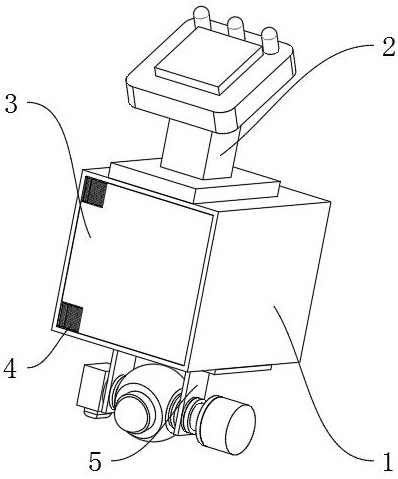
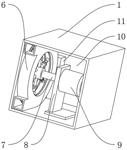
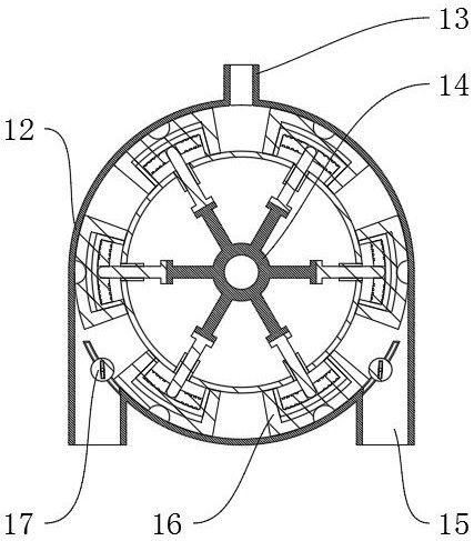
[0041] A home environment monitoring device based on the Internet of Things, such as Figure 1-Figure 8 As shown, it includes a main frame 1, the top outer wall of the main frame 1 is fixedly connected with a control terminal 2, the inside of the main frame 1 is fixedly connected with a ring receiving mechanism 6, and the bottom outer wall of the main frame 1 is fixedly connected with a video recording assembly 5; The mechanism 6 includes an inner frame 12 and six split components 16, and two delay components 17 are fixedly connected inside the inner frame 12; the inner frame 12 is a ring structure, and two airflow connection pipes 15 are provided on the outer wall of one side of the inner frame 12, The outer wall on the other side of the inner frame 12 is provided with an analysis adapter 13, and the outer wall on one side of the analysis adapter 13 is fixedly connected with an analyzer 11. The partition assembly 16 includes a closing block 21 and an inner sleeve 22. The closi...

Embodiment 2

[0045] A method for a home environment monitoring device based on the Internet of Things, comprising the steps of:

[0046] S1: Segmentation area; the power motor 9 starts to drive the mandrel 7 to rotate, and the six segmentation components 16 divide the inner wall space of the inner frame 12 into six areas, and each area can independently store gas, which is analyzed by the analyzer 11;

[0047] S2: Negative pressure absorption; when the segmented assembly 16 at the intake end approaches, the clamping ball 29 will snap into the outer wall of one side of the closing block 21, so that the movement of the closing block 21 lags behind the sliding column 24, thereby expanding the gap between two adjacent closing blocks 21 The distance between them expands the space, forms a negative pressure zone, and accelerates air absorption;

[0048] S4: pressurized discharge; at the other outlet end, due to the lagging movement of the closed block 21, the distance between two adjacent closed...


PUM


Abstract

The invention discloses a home environment monitoring device and method based on the Internet of Things, and relates to the field of environmental monitoring; in order to solve the problem of low gas analysis efficiency of existing devices; the device specifically includes a main frame, and the top outer wall of the main frame is fixed It is connected with a control terminal, and the inside of the main frame is fixedly connected with a looping mechanism, and the outer wall of the bottom of the main frame is fixedly connected with a video component, and the looping mechanism includes an inner frame and six split components. In the present invention, the main frame is set, the power motor is started, the mandrel is driven to rotate, the connecting column is driven to rotate through the sleeve, and the partition assembly is driven to rotate, wherein the six partition assemblies divide the inner wall space of the inner frame into six regions, and each region can be independently The gas is stored and analyzed by the analyzer. At the same time, through the continuous operation of the power motor, the analyzed gas can be sent out through the gas flow pipe, realizing the alternation of relatively closed and flowing gas, and improving the efficiency of data collection.

Description

technical field [0001] The invention relates to the field of environment monitoring, in particular to an Internet of Things-based home environment monitoring device and method. Background technique [0002] With the blessing of the Internet of Things platform, data integration analysis has been greatly applied, but the accuracy of terminal data source acquisition needs to be strictly guaranteed, especially in the field of home environment monitoring, terminal devices need to be innovated to meet the needs of data update frequency. [0003] After searching, the Chinese patent application number is 201810180484.0, which discloses a portable home environment monitoring device, which has a square shell, and a peak-shaped top cover is fixed on the top of the square shell, and the upper end surface of the peak-shaped top cover is set. Air suction port; horizontal beams are set in the square shell, and micro motors are vertically set in the middle of the beams. A temperature senso...

Claims


Application Information

Patent Timeline
Patent Type & Authority Patents(China)
IPC IPC(8): G01N33/00H04N5/232H04N5/76
CPCG01N33/0009G01N33/0067H04N5/76H04N23/695
Inventor 张祥生周涵颖邢盼盼
Owner 汶上县郭楼镇为民服务中心(汶上县郭楼镇退役军人服务站)
Learn More