End face grinding device for wind wheel blade machining

A technology for end face grinding and wind rotor blades, which is used in grinding/polishing safety devices, machine tools suitable for grinding workpiece planes, grinding workpiece supports, etc. Inconsistent end face shape, displacement and other problems, to achieve the effect of speeding up the processing progress, ensuring firmness, and preventing displacement

Pending Publication Date: 2021-12-14
翟红霞
View PDF7 Cites 0 Cited by
  • Summary
  • Abstract
  • Description
  • Claims
  • Application Information

AI Technical Summary

Problems solved by technology

[0004] The purpose of the present invention is to provide a kind of end surface grinding device for wind rotor blade processing, to solve the above-mentioned background technology that the end surface shape of the wind rotor blades in the market is inconsistent, so it is not convenient to fix the blade during grinding, resulting in It is easy to shift during grinding, and it is not convenient to grind multiple blades at the same time, which reduces the processing progress of the blades. The waste generated during the blade grinding process is not easy to clean up, and it is easy to affect the surrounding environment. Thereby reducing the problem of the efficiency of the use of the grinding device

Method used


Image

  • End face grinding device for wind wheel blade machining
  • End face grinding device for wind wheel blade machining
  • End face grinding device for wind wheel blade machining

Examples


Embodiment Construction

[0035] The following will clearly and completely describe the technical solutions in the embodiments of the present invention with reference to the accompanying drawings in the embodiments of the present invention. Obviously, the described embodiments are only some, not all, embodiments of the present invention. Based on the embodiments of the present invention, all other embodiments obtained by persons of ordinary skill in the art without making creative efforts belong to the protection scope of the present invention.

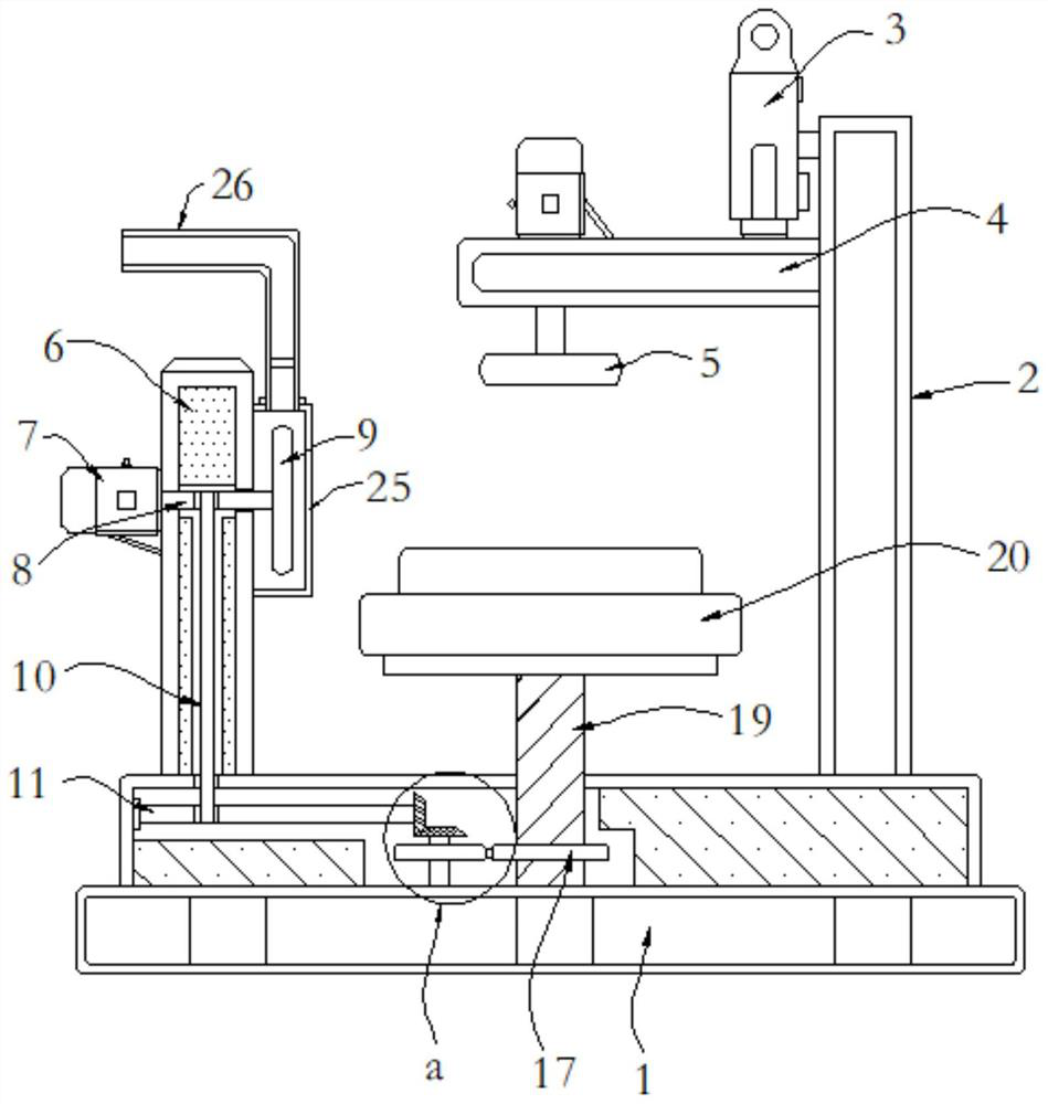
[0036] see Figure 1-7 , the present invention provides a technical solution: an end grinding device for wind turbine blade processing, the base 1 is placed on the ground, the first column 2 is fixed on the upper right side of the base 1, and the inner wall of the first column 2 The upper bolt is equipped with a hydraulic cylinder 3;

[0037] The second column 6 is arranged on the upper left side of the base 1, and the bolt on the outer wall of the second col...


PUM


Abstract

The invention discloses an end face grinding device for wind wheel blade machining. A base is placed on the ground, a first stand column is fixed to the right side of the upper portion of the base, and a hydraulic cylinder is installed on the inner wall of the first stand column through bolts; a second stand column is arranged at the left side of the upper portion of the base, and a driving motor is installed on the outer wall of the second stand column through bolts; the device comprises a transverse plate and a second connecting disc, the top end of the transverse plate is connected with the output end of a hydraulic cylinder, and a grinding wheel is arranged below the transverse plate; and the second connecting disc is arranged at the right side of the first rotating rod, and a clamping groove is formed in the second connecting disc. According to the end face grinding device for wind wheel blade machining, a containing groove is formed in the inner wall of a containing plate, a fixing suction cup is arranged in the containing groove, an elastic spring is installed at the bottom of the fixing suction cup, and meanwhile the containing groove is in a trapezoid shape, so that different positions of a blade can be adsorbed and fixed conveniently; and therefore, the firmness of blade grinding in the later period is ensured.

Description

technical field [0001] The invention relates to the technical field of wind rotor blade processing, in particular to an end surface grinding device for wind rotor blade processing. Background technique [0002] Wind rotor blades refer to the equipment used in wind energy utilization. They are generally installed on the rotating shaft, and the blades are driven to rotate through the rotating shaft. There are many types and sizes of blades on the market, and corresponding choices can be made according to different applications. [0003] For example, the publication number is CN102990488B, a wind turbine blade end grinding machine, including a main engine, a control cabinet and a hydraulic station, adopts a support and fixing frame structure, which can be fixed in the inner cavity of the blade root during grinding, does not occupy space, and does not require However, there are still some deficiencies in the existing end face grinding device for processing wind turbine blades. B...

Claims


Application Information

Patent Timeline
Patent Type & Authority Applications(China)
IPC IPC(8): B24B19/14B24B7/16B24B41/06B24B41/00B24B55/12
CPCB24B19/14B24B7/16B24B41/06B24B41/00B24B55/12
Inventor 翟红霞
Owner 翟红霞
Why Eureka
Try Eureka