New energy compartment type mobile emergency charging vehicle
An emergency charging and new energy technology, applied in electric vehicle charging technology, charging stations, motor vehicles, etc., can solve the problems of generator power influence, vibration and insufficient power, and achieve the effect of facilitating charging and ensuring power
- Summary
- Abstract
- Description
- Claims
- Application Information
AI Technical Summary
Problems solved by technology
Method used
Image
Examples
Embodiment 1
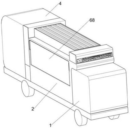
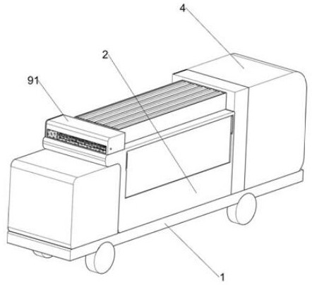
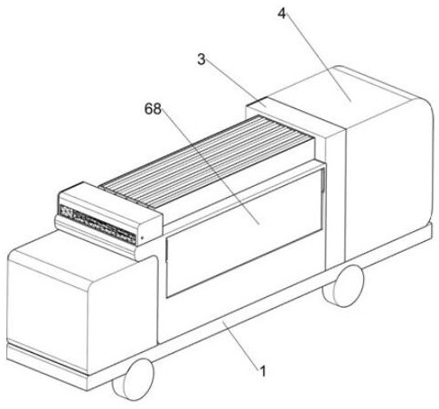
[0044] A new energy van-type mobile emergency charging vehicle, such as figure 1 , figure 2 , image 3 , Figure 4 , Figure 5 , Figure 6 , Figure 7 , Figure 8 , Figure 9 and Figure 10 As shown, it includes an emergency charging transport vehicle 1, a battery compartment 2, a motor compartment 3, a power generation compartment 4, a protection frame 5, an opening and closing assembly 6, and a charging assembly 7. The emergency charging transport vehicle 1 is fixed above the battery compartment 2. The motor compartment 3 is fixedly connected above the charging transport vehicle 1, and the motor compartment 3 is located on the left side of the battery compartment 2. The power generation compartment 4 is fixedly connected above the emergency charging transport vehicle 1. Electric energy is stored in the power generation compartment 4, and the power generation compartment 4 is located on the motor compartment 3. On the left side, the top of the battery compartment 2 i...
Embodiment 2
[0049] On the basis of Example 1, such as Figure 11 , Figure 12 , Figure 13 and Figure 14 As shown, also includes a solar power generation assembly 8, the solar power generation assembly 8 is located on the protective frame 5, the solar power generation assembly 8 is used to supplement electric energy to the battery in an emergency, the solar power generation assembly 8 includes a fixed gear 81, a fixed groove plate 82, a mobile Rack 83, fixed rack 84, movable rod 85, movable sealing plate 86, rotating gear 87 and solar photovoltaic panel 88, the power shaft 64 at the rear side is fixedly connected with fixed gear 81 near the motor compartment 3, and the protective frame 5 The left side of the outside is fixedly connected with a fixed slot plate 82, and the fixed slot plate 82 is slidably connected with a moving rack 83, the moving rack 83 is located above the fixed gear 81, the moving rack 83 meshes with the fixed gear 81, and the top of the moving rack 83 The rack 84 ...
Embodiment 3
[0052] On the basis of Example 2, such as Figure 15 and Figure 16 As shown, it also includes a wind power generation assembly 9, the wind power generation assembly 9 is located on the right side of the top of the battery compartment 2, and the wind power generation assembly 9 is used to supplement the battery in the battery compartment 2 to prevent the battery in the battery compartment 2 from being used for a long time. And cause its electric power loss situation, wind power generating assembly 9 comprises top shell 91, wind shaft 92, rotating blade 93, metal grid frame 94, support 95, wind power generator 96 and air outlet 97, battery compartment 2 top right The top shell 91 is fixedly connected to the top shell 91, and the left side of the top shell 91 has a rectangular through hole with a slope to prevent rainwater from entering the inside of the top shell 91. The inside of the top shell 91 is connected to the wind shaft 92 in a rotating manner, and the wind shaft 92 is ...
PUM
 Abstract
Description
Claims
Application Information
 - R&D
- Intellectual Property
- Life Sciences
- Materials
- Tech Scout
- Unparalleled Data Quality
- Higher Quality Content
- 60% Fewer Hallucinations
Browse by: Latest US Patents, China's latest patents, Technical Efficacy Thesaurus, Application Domain, Technology Topic, Popular Technical Reports.
© 2025 PatSnap. All rights reserved.Legal|Privacy policy|Modern Slavery Act Transparency Statement|Sitemap|About US| Contact US: help@patsnap.com


