Bamboo laminated wood frame structure beam-column joint
A technology of beam-column joints and frame structures, which is applied to truss structures, columns, girders, etc., can solve the problems of inability to resist bending moments and horizontal loads, inconvenient building use, and inability to form open building spaces, so as to achieve saving The effect of bamboo, open building space and convenient processing
- Summary
- Abstract
- Description
- Claims
- Application Information
AI Technical Summary
Problems solved by technology
Method used
Image
Examples
Embodiment 1
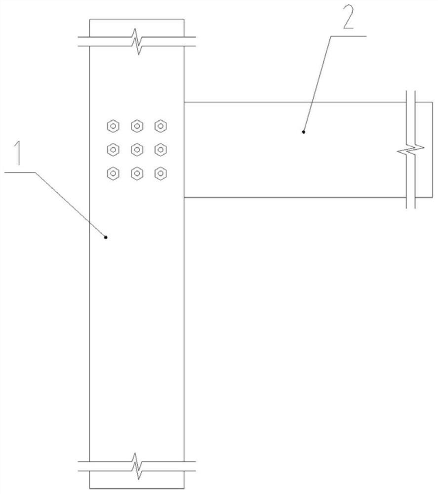
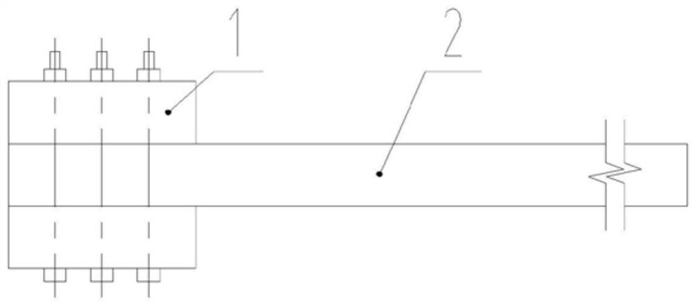
[0021] Embodiment one, as figure 1 , figure 2 As shown, the bamboo glulam frame structure beam-column node disclosed in this embodiment includes double-leg columns 1 and horizontal beams 2, and one end of the horizontal beam 2 is clamped between the two-leg columns 1 and arranged in a square matrix. The high-strength bolt and nut components are connected and fixed.
[0022] This beam-column joint cannot bear horizontal loads and needs to be used in conjunction with shear walls or supports. However, this joint has a simple structure, convenient construction, beautiful joints, and takes up less indoor space. It is suitable for frame structures with shear walls or supports.
Embodiment 2
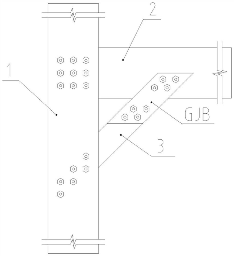
[0023] Embodiment two, such as image 3 , Figure 4 As shown, in this embodiment, a diagonal brace 3 is added between the double-leg column 1 and the horizontal beam 2 on the basis of the first embodiment.
[0024] The lower part of the brace 3 is clamped in the two-leg columns 1, and is connected and fixed with the two-leg columns 1 by bolts and nuts arranged in a square matrix. The top surface of the upper part of the diagonal brace 3 is supported on the bottom surface of the horizontal beam 2, and steel splints 4 are set on both sides to clamp the two sides of the horizontal beam 2. Arranged bolt and nut assemblies are connected and fixed.
[0025] The angle between the diagonal brace 3 and the double-leg column 1 is small, and the structure of this node can bear the horizontal load, but the existence of the diagonal brace at this node may cause the node to be unsightly or affect the usable space. It can be selected according to the actual situation.
Embodiment 3
[0026] Embodiment three, such as Figure 5 As shown, the difference between this embodiment and the second embodiment is that the angle between the diagonal brace 3 and the double-leg column 1 is relatively large, and the width of the diagonal brace 3 increases, so the bearing capacity is larger than that of the second embodiment, but the ductility is higher than that of the second embodiment. Second, the horizontal beam 2 is easy to be damaged by the tensile force of the transverse grain, and the diagonal brace 3 is generally not damaged due to its large cross-section. It is suitable for non-earthquake areas and is not suitable for buildings with relatively high ductility requirements in earthquake areas.
PUM
 Abstract
Description
Claims
Application Information
 - R&D
- Intellectual Property
- Life Sciences
- Materials
- Tech Scout
- Unparalleled Data Quality
- Higher Quality Content
- 60% Fewer Hallucinations
Browse by: Latest US Patents, China's latest patents, Technical Efficacy Thesaurus, Application Domain, Technology Topic, Popular Technical Reports.
© 2025 PatSnap. All rights reserved.Legal|Privacy policy|Modern Slavery Act Transparency Statement|Sitemap|About US| Contact US: help@patsnap.com


