Special dyeing device for diagnosis of pathology department
A special staining and pathological technology, applied in the field of pathology staining, can solve the problems of glass bump damage, object damage, shaking, etc., to improve the utilization rate, reduce human operations, and reduce the leakage of harmful gases.
- Summary
- Abstract
- Description
- Claims
- Application Information
AI Technical Summary
Problems solved by technology
Method used
Image

Examples
Embodiment 1
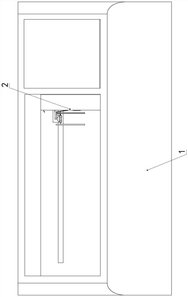
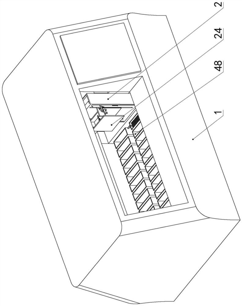
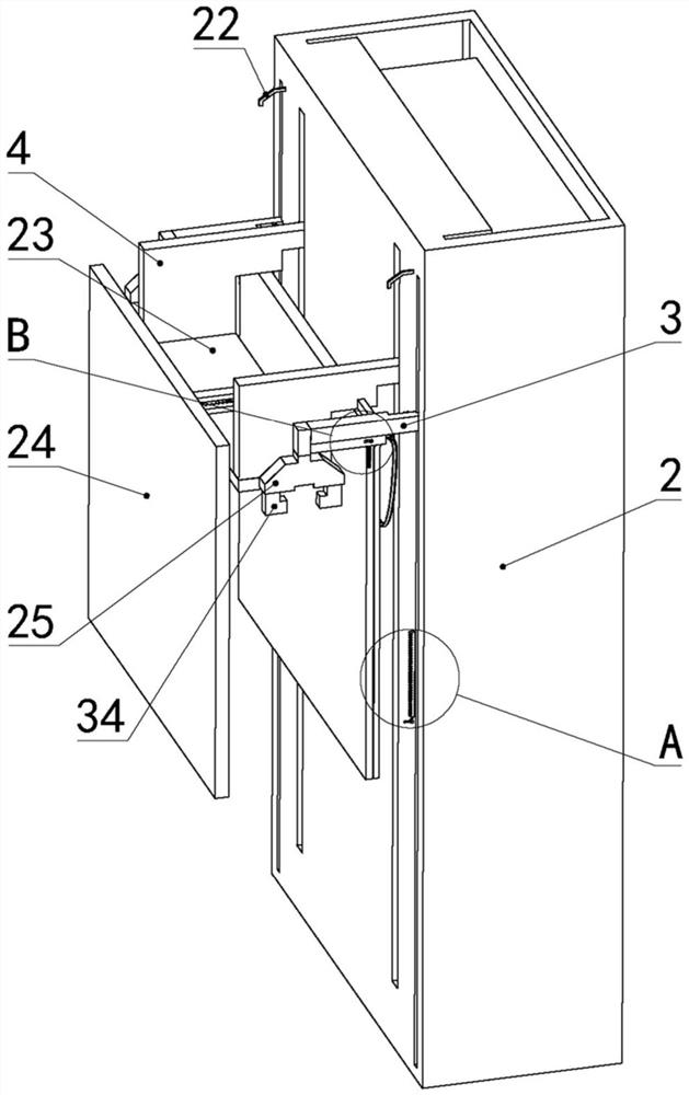
[0034] , Special staining apparatus for the diagnosis of a pathology in Example 1, comprises a main body frame 11, is a dyeing machine body frame 1 embodiment, for example, pathological Dakota dyeing machine, opened on the main body frame 1 has a transverse electric rail inside, with electric sliding guide frame overhang, the guide rail extending in front of the electric rack, rack mounted projecting projecting cylinder, the cylinder projecting longitudinal stretching direction, the carriage 2 is mounted on the projecting cylinder, the slide 2 have the mount-cylinder, rodless cylinders slide vertically reciprocating slide, fixed to the support rod 3 is connected to two lateral jaws provided on the slider of the rodless cylinder, the support bar 3 is located in jaw rodless the left side of the cylinder, and two support rods 3 pairs of jaws disposed front and rear sides of the rodless cylinder; the two support rods 3-one correspondence jaws clamp the carriage 2 supporting bar 4, sup...
Embodiment 2
[0035] Example 2 In Example 1 based on the embodiment, the gripping mechanism includes a gripper housing 25, the housing jaw 25 is fixedly connected to the jaw support bar 3, defines a hermetically sealed cavity 26 within the jaw housing 25, air-tight chamber 26 is located in the upper jaw clamp housing 25, gas-tight seal the chamber 26 vertically slidably connected to the piston block 27, the upper end of the piston block 27 and the jaw housing 25 is connected with a vertical first return spring 28 the first return spring 28 and the upper end of the jaw housing 25 is fixedly connected to the lower end of the first return spring 28 and the piston block 27 is fixedly connected to the lower end of the piston block 27 is fixed to a vertical rod 29, the lower end of the piston rod 29 along the sealing slide vertically through the housing 25 and the lower jaw in an airtight cavity 26, 25 on the jaw housing 30 defines a laterally disposed airway, the airway and external air compressor 3...
Embodiment 3
[0036] Example 3, based on embodiment 2, the groove defines a recovery of the carriage 2, the second rack 16 in the lateral sliding fit in the retracted second tooth groove, the second rack teeth 16 is located Article 16 of the left end, the left end of the second rack 16 extending grooves retracted, and a second return spring is connected between the carriage 2 and the right end of the second rack 16, the second return spring disposed laterally disposed second return spring recovery tank, the second return spring is fixedly connected to the left end of the right end of the second rack 16, the right end of the second return carriage 2 is fixedly connected to the spring; right second rack 16 are attached to the carriage 2, magnetic chuck, is mounted on the body frame 1 has electrical connections between the control module, control module and an electromagnetic chuck, a right end of the second rack 16 iron plating process; when energized electromagnetic sucker, sucker electromagneti...
PUM
 Abstract
Description
Claims
Application Information
 - R&D
- Intellectual Property
- Life Sciences
- Materials
- Tech Scout
- Unparalleled Data Quality
- Higher Quality Content
- 60% Fewer Hallucinations
Browse by: Latest US Patents, China's latest patents, Technical Efficacy Thesaurus, Application Domain, Technology Topic, Popular Technical Reports.
© 2025 PatSnap. All rights reserved.Legal|Privacy policy|Modern Slavery Act Transparency Statement|Sitemap|About US| Contact US: help@patsnap.com