Improved broadband parallel receiver timing synchronization method

A timing synchronization and receiver technology, applied in the direction of synchronization devices, synchronization/start-stop systems, baseband systems, etc., can solve the problems of communication quality degradation, signal-to-noise ratio degradation of received signals, etc., achieve fast convergence characteristics, and are not easy to lose lock Effect

Pending Publication Date: 2021-12-14
NO 20 RES INST OF CHINA ELECTRONICS TECH GRP
View PDF0 Cites 0 Cited by
  • Summary
  • Abstract
  • Description
  • Claims
  • Application Information

AI Technical Summary

Problems solved by technology

The purpose of the present invention is to propose a method for estimating and compensating timing errors in a parallel architecture for wireless communication broadband signals due to the decrease in the signal-to-noise ratio of the received signal at the receiving end due to the clock deviation of the analog-to-digital converter, thereby reducing the communication quality.

Method used


Image

  • Improved broadband parallel receiver timing synchronization method
  • Improved broadband parallel receiver timing synchronization method
  • Improved broadband parallel receiver timing synchronization method

Examples


Embodiment 1

[0040] Step 1, initialize m=0, δ=0, in this example the matched filter coefficient H(k), k=1,2,...64, is the root raised cosine filter with a roll-off coefficient of 0.4, the matched filter coefficient H(k) is the result of 64-point Fourier transform, which is a 64-bit complex vector and remains unchanged during the entire algorithm operation. The filter initialization for timing phase correction is 1 for bits 1 to 16, 0 for bits 17 to 49, and 1 for bits 50 to 64. Initialize timing error estimation real part Re=0, imaginary part Im=0, timing error estimation times count=0, cumulative timing error ε sum =0, the timing error ε=0 after loop filtering.

[0041] Step 2: Output 32 data from the I-channel FIFO and Q-channel FIFO respectively, and perform 64-bit FFT by using the overlap-save method or overlap-add method, and obtain the result X of the 64-bit FFT I (k) and X Q (k). Will X I (k) and X Q(k) and the matched filter coefficient H(k) are multiplied in pairs. The resul...

Embodiment 2

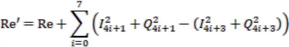
[0051] Step 4, calculate the timing error phase angle

[0052]

[0053] Assuming that count is 31, Re=20.8, Im=3.898, then the timing error phase angle Go to step 5.

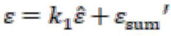
[0054] Step 5, perform loop filtering, loop filter coefficient Cumulative timing error ε sum and the timing error ε after loop filtering is calculated according to the following formula

[0055]

[0056]

[0057] by For example, ε=-0.0166 after loop filtering.

[0058] Step 6, judge whether ε is greater than 1 or less than -1, if ε>1, then ε=ε-1, m=1; if ε<-1, then ε=ε+1, m=-1; in other cases ε Remain unchanged, m=0. Since ε=-0.0166, m=0, go to step 7.

[0059] Step 7, modifying the timing phase correction filter coefficients to control the FIFO output.

[0060] The 1st to 16th bits of the corrected timing phase correction filter coefficients are e j2πs(k-1) / 64 , where k=1, 2, ..., 16. Bits 17 to 49 remain 0, and bits 50 to 64 are e -j2πs(64-k+1) / 64 , where k=51, 52,..., 64, ε=-0.0166, th...

Embodiment 3

[0064] When the calculation of the timing error in step 5 shows that ε is less than -1, take ε=-1.0928 as an example.

[0065] Step 6, judge whether ε is greater than 1 or less than -1, if ε>1, then ε=ε-1, m=1; if ε<-1, then ε=ε+1, m=-1; in other cases ε Remain unchanged, m=0. Since ε=-1.0928, ε=-1.0928+1=-0.0928, m=-1, go to step 7.

[0066] Step 7, modifying the timing phase correction filter coefficients to control the FIFO output.

[0067] The 1st to 16th bits of the corrected timing phase correction filter coefficients are e j2π(-0.0928)(k-1) / 64 , where k=1, 2, ..., 16. Bits 17 to 49 remain 0, and bits 50 to 64 are e -j2π(-0.0928)(64-k+1) / 64 , where k=51, 52, . . . , 64. Because m=-1, I road and Q road FIFO need last data output last time as the first data of this output, and all the other data are pushed back successively, with I -1 (n) represents the data that the previous I road FIFO outputs, and n represents the position of the previous moment data in the FIFO, a...


PUM


Abstract

The invention provides an improved broadband parallel receiver timing synchronization method, which comprises the following steps of: performing timing error estimation by using receiving data, compensating phase deviation caused by clock error by correcting a timing phase correction filter coefficient, and correcting frequency deviation caused by the clock error by controlling FIFO output. According to the improved broadband parallel receiver timing synchronization method, the problems of sampling time offset, reduced signal-to-noise ratio and unreliable transmission caused by inaccurate clock of the analog-to-digital converter are solved. The improved broadband parallel receiver timing synchronization method is more suitable for broadband signals transmitted at a high speed, and can also be used for a receiver with a serial architecture through modification, so that the algorithm has a faster convergence characteristic, and the adopted correction timing phase correction filter coefficient is not easy to lose lock after optimization design and convergence.

Description

technical field [0001] The invention relates to the field of broadband wireless communication digital signal processing, and mainly solves the problem of deterioration of transmission quality caused by the deviation of the best sampling point caused by the clock error of the analog-to-digital converter in the wireless communication system. Specifically, it is a method for estimating the sampling frequency error of an analog-to-digital converter based on a received signal and compensating in the frequency domain, which is used for broadband digital signal processing in wireless communication. Background technique [0002] Due to the limitations of the performance of analog devices, there is a certain deviation in the clock frequency of the analog-to-digital converter of the wireless communication receiver, which causes the digital sampling point to not necessarily be at the peak point of the symbol, resulting in a decrease in the signal-to-noise ratio at the receiving end. In...

Claims


Application Information

Patent Timeline
Patent Type & Authority Applications(China)
IPC IPC(8): H04W56/00H04L25/02H04L25/38H03H17/02
CPCH04W56/001H04L25/0214H04L25/38H03H17/0248
Inventor 吴道龙文明王瑜迟凯茅迪徐媛媛郭褚冰赵熙李晓冬
Owner NO 20 RES INST OF CHINA ELECTRONICS TECH GRP
Why Eureka
Try Eureka