Robotic Force/Torque Sensor with Controlled Thermal Conduction

A technology of torque sensor and manpower, applied in force/torque/work measuring instrument, force/torque/work measuring instrument calibration/testing, instruments, etc. Ability to model signal components, the effect of increasing effectiveness

Pending Publication Date: 2021-12-17
奥腾工业自动化(廊坊)有限公司
View PDF3 Cites 0 Cited by
  • Summary
  • Abstract
  • Description
  • Claims
  • Application Information

AI Technical Summary

Problems solved by technology

[0015] In general, these techniques work best when the temperature variation is uniform across the body of the force / torque sensor - which is rarely the case in practical applications

Method used


Image

  • Robotic Force/Torque Sensor with Controlled Thermal Conduction
  • Robotic Force/Torque Sensor with Controlled Thermal Conduction
  • Robotic Force/Torque Sensor with Controlled Thermal Conduction

Examples


Embodiment Construction

[0026] For purposes of simplicity and illustration, the invention has been described primarily by reference to exemplary embodiments thereof. In the following description, numerous specific details are set forth in order to provide a thorough understanding of the present invention. However, it will be readily apparent to one of ordinary skill in the art that the present invention may be practiced without limitation to these specific details. In this description, well-known methods and structures have not been described in detail so as not to unnecessarily obscure the present invention.

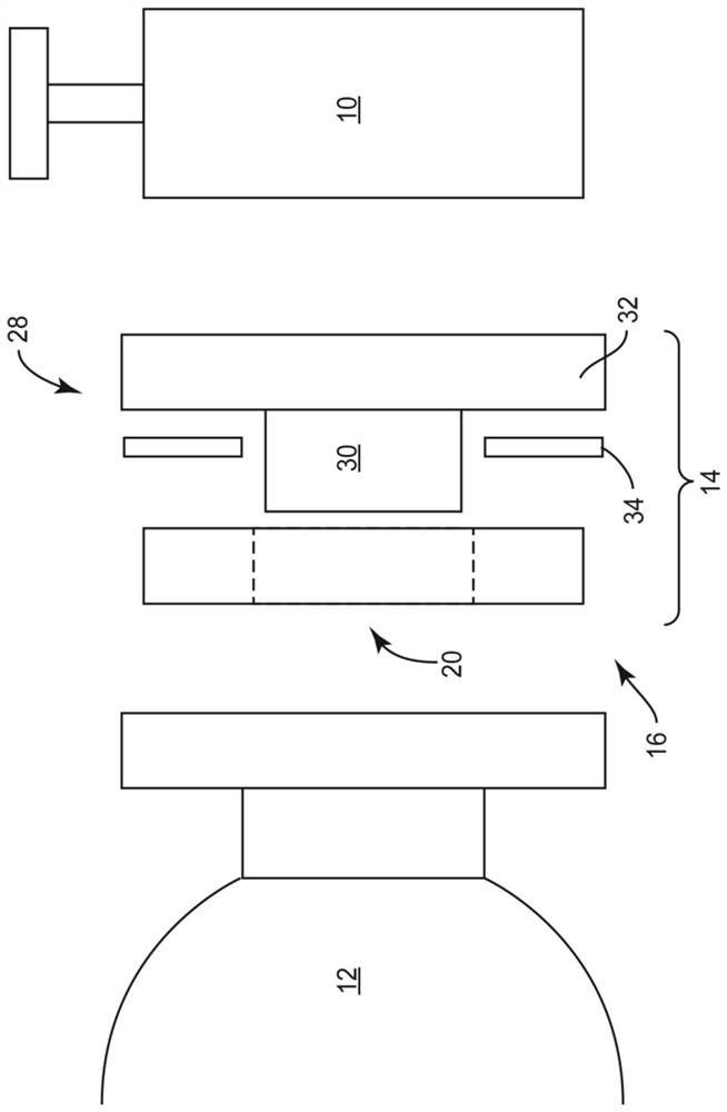
[0027] figure 1 is an exploded cross-sectional view of a typical tool 10 , such as a grinder, attached to a robotic arm 12 , such as may be deployed in a factory or other application. A robot force / torque (FT) sensor 14 is interposed between the tool 10 and the robot 12 . The FT sensor 14 measures the forces and torques between the robot 12 and the tool 10, ie when the robot 12 presses the ...


PUM


Abstract

A robotic force/torque (FT) sensor restricts the conduction of heat, generated by an attached tool, through the FT sensor body to a radial direction. Heat from the tool is channeled to the center of the FT sensor body by a thermally conductive member. Additionally, heat from the tool is insulated from portions of the FT sensor body other than its center by a thermally insulating member. Transducers, such as strain gages attached to the surfaces of deformable beams, are disposed at a substantially equal distance from the center of the FT sensor body. Accordingly, as heat conducts through the FT sensor body from the center radially outwardly, all transducers experience substantially equal thermal load at any given time. Embodiments of the present invention substantially eliminate thermal gradients across groups of transducers that are wired in differential circuit topologies, such as half-bridge or quarter-bridge, enhancing the ability of such circuits to reject a common-mode signal component caused by thermal changes to the FT sensor body or the transducers themselves. Elimination of thermal gradients in the FT sensor body, other than one in the radial direction, enhances the effectiveness of known temperature compensation techniques.

Description

[0001] Cross References to Related Applications [0002] This application claims priority to U.S. Patent Application No. 16 / 902,674, filed June 16, 2020, entitled "Robotic Force / Torque Sensor with Controlled Thermal Conduction," the disclosure of which is incorporated herein by reference in its entirety. technical field [0003] The present invention relates generally to force / torque sensors for robotic applications, and in particular to force / torque sensors having a predictable distribution of heat throughout the sensor body during operation. Background technique [0004] Robotics is a growing and increasingly important field in industrial, medical, scientific, aerospace and other applications. In many instances where a robotic arm or a tool attached to it comes into contact with a workpiece, the applied force and / or torque must be closely monitored. Therefore, force / torque sensors are an important part of many robotic systems. [0005] Many types of force / torque sensors ...

Claims


Application Information

Patent Timeline
Patent Type & Authority Applications(China)
IPC IPC(8): B25J13/08
CPCB25J13/085G01L1/26G01L5/226B25J19/0054G01L5/0066G01L19/04G01L19/0681G01L1/2281G01L3/108G01L25/00B25J15/0019
Inventor J·利普赛
Owner 奥腾工业自动化(廊坊)有限公司
Why Eureka
Try Eureka