
Concrete member production line

A production line and concrete technology, applied in the field of concrete component production line, can solve the problems of low degree of automation, affecting the efficiency of concrete component production, and spending a lot of time, so as to achieve the effect of improving efficiency

Active Publication Date: 2021-12-17
南京交通工程有限公司
View PDF6 Cites 0 Cited by
  • Summary
  • Abstract
  • Description
  • Claims
  • Application Information

AI Technical Summary

Problems solved by technology

[0004] At present, in the production of concrete components, due to the low degree of automation, most of them use manual demoulding to demould concrete components. The inventor believes that when the volume of concrete components is small and the number is large, it will take a lot of time to use manual demoulding. , which seriously affects the efficiency of concrete member production

Method used


Image

  • Concrete member production line
  • Concrete member production line
  • Concrete member production line

Examples


Embodiment Construction

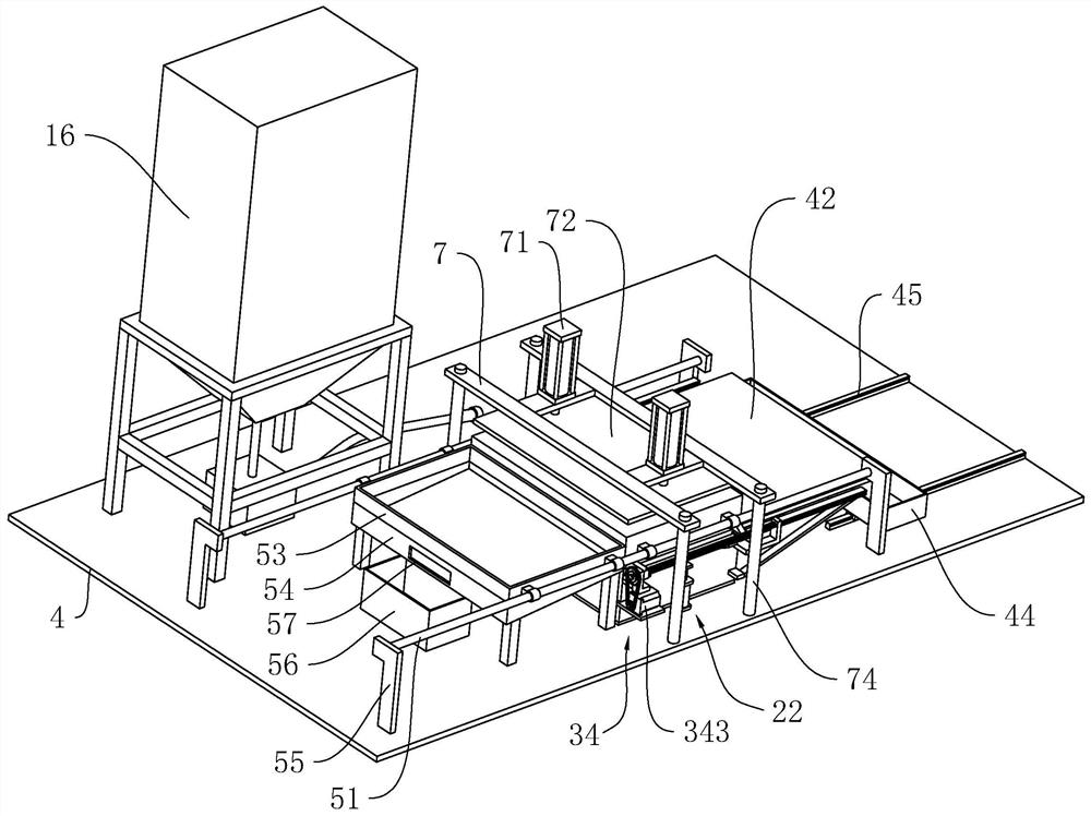
[0041] The following is attached Figure 2-8 The application is described in further detail.

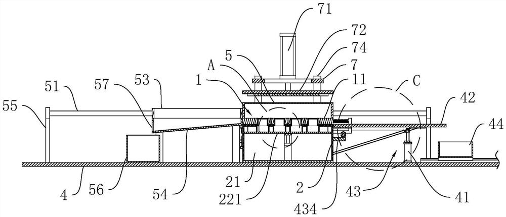
[0042] The embodiment of the application discloses a concrete member production line. Such as figure 2 and image 3 , the concrete member production line includes a bottom plate 4 horizontally arranged on the ground, a rectangular base 2 is arranged on the bottom plate 4, a mold 1 is arranged on the upper surface of the base 2, a curing device is arranged on the mold 1, and a mold 1 is arranged on the ground. The pouring equipment 16 for pouring concrete, the base 2 is provided with a blanking device along one side of its width direction, and the base 2 is provided with a demoulding device, wherein the pouring equipment 16 is a prior art and will not be described too much.

[0043] Such as Figure 4 , Figure 5 as well as Figure 6 , the mold 1 includes a rectangular outer mold 11, the base 2 is fixedly connected with slide rails 32 on both sides along its own length direction, ...


PUM


Abstract

The invention relates to the technical field of concrete member machining, in particular to a concrete member production line. The concrete member production line comprises pouring equipment, a mold, a base, a curing device and a demolding device, wherein the mold comprises an outer mold and inner molds, the outer mold is arranged on the base, a plurality of pouring cavities are formed in the outer mold, the inner molds correspond to the pouring cavities in a one-to-one mode, and all the inner molds are arranged in the corresponding pouring cavities; and the demolding device comprises demolding plates, the demolding plates correspond to the pouring cavities in a one-to-one mode, all the demolding plates are embedded in the base, a cavity is formed in the base, and a lifting component used for driving the demolding plates to ascend and descend is arranged in the cavity. The concrete member production line has the effect of improving the production efficiency of concrete members.

Description

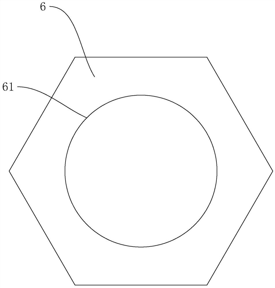
technical field [0001] The present application relates to the field of concrete component processing technology, in particular to a concrete component production line. Background technique [0002] Slope protection bricks are commonly used on slopes to strengthen the stability of regional soil, reduce landslides caused by rainwater, and ensure the safety of pedestrians. [0003] Such as figure 1 , The slope protection brick 6 is a kind of concrete member, the slope protection brick 6 is a regular hexagon, and the middle position of the slope protection brick 6 is provided with a circular through hole 61 . [0004] At present, in the production of concrete components, due to the low degree of automation, most of them use manual demoulding to demould concrete components. The inventor believes that when the volume of concrete components is small and the number is large, it will take a lot of time to use manual demoulding. , seriously affecting the efficiency of concrete membe...

Claims


Application Information

Patent Timeline
IPC IPC(8): B28B7/18B28B7/24B28B13/06B28B13/04B28B17/00
CPCB28B7/183B28B7/24B28B13/06B28B13/04B28B17/00
Inventor 朱牛锁韩海波
Owner 南京交通工程有限公司
Learn More