
Horizontal pushing type gear shifting mechanism and system

A shift mechanism, flat-push technology, applied in mechanical equipment, components with teeth, belts/chains/gears, etc., can solve the problems of mechanical wear, complex structure, affecting performance, etc., to achieve long service life, simplified Structure, enhance the effect of lightweight

Pending Publication Date: 2021-12-17
GUANGZHOU AUTOMOBILE GROUP CO LTD
View PDF0 Cites 0 Cited by
  • Summary
  • Abstract
  • Description
  • Claims
  • Application Information

AI Technical Summary

Problems solved by technology

The shifters of the above methods all have existing solutions with a reset function, but the existing reset functions are all reset through the mechanical reset structure of the bullet, spring and gear slot, and the noise is relatively large when shifting gears. And the size is large, the structure is complex, the cost is high, and the use time will cause mechanical wear and affect the performance

Method used


Image

  • Horizontal pushing type gear shifting mechanism and system
  • Horizontal pushing type gear shifting mechanism and system
  • Horizontal pushing type gear shifting mechanism and system

Examples


no. 1 example

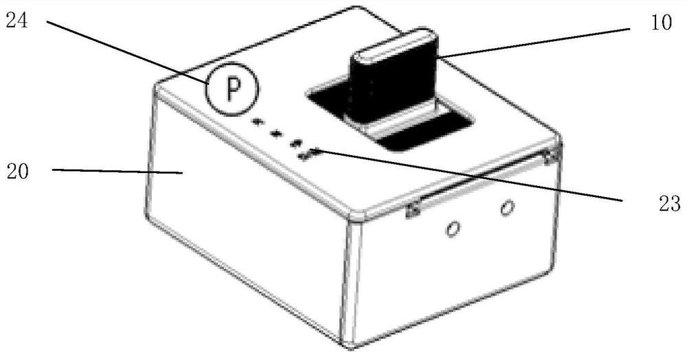
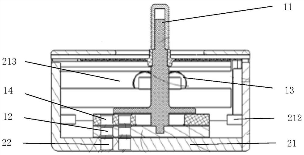
[0029] Please refer to Figure 1 to Figure 7 , the first embodiment of the present invention is a flat-push shift mechanism for shift-by-wire vehicles, including a shift lever assembly 10 and a base assembly 20 . The shift rod assembly 10 includes a rod body 11, a bearing group 13, a first magnetic element 12 and a third magnetic element 14 fixed on the rod body 11, and the base assembly 20 includes a base body 21, a second magnetic element fixed on the base body 21 Magnetic element 22, and gear display device 23.

[0030] The bearing set 13 includes at least one bearing, and the base body 21 is provided with a limiting groove 213 , and the bearing is installed in the limiting groove 213 with an interference fit. The inner ring of the bearing is fixed on the rod body 11, the outer ring of the bearing is in contact with the seat body 21, the bearing group 13 is used to make the shift lever assembly 10 slide on the base assembly 20, and the limit groove 213 is used to make the ...

no. 2 example

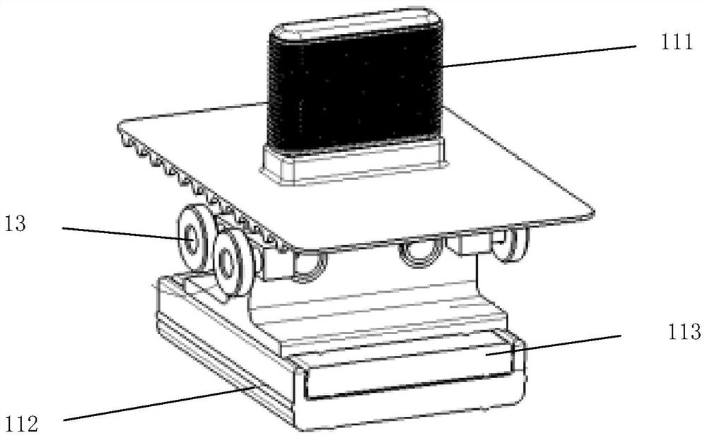
[0047] Please refer to Figure 8 to Figure 10 The difference between the second embodiment of the present invention, a flat-push shift mechanism, and the above-mentioned first embodiment is that in this embodiment, the rod body 11 only includes a handle 111 and a first sliding piece 112 fixedly connected to the end of the handle 111 , the moving position includes the front first position and the rear first position.

[0048] Other parts such as the bearing group 13 and the detection device are consistent with the first embodiment. The polarity of the first magnetic element 12 is opposite to that of the second magnetic element 22 , and the shift lever assembly 10 is located at the initial position under the action of the attractive force of the first magnetic element 12 and the second magnetic element 22 . The first sliding piece 112 can slide forward and backward in the base assembly 20 when the handle 111 is pushed by an external force, and can reach the first front position...


PUM


Abstract

The invention discloses a horizontal pushing type gear shifting mechanism which is used for a drive-by-wire gear shifting automobile. The horizontal pushing type gear shifting mechanism comprises a gear shifting rod assembly and a base assembly, the gear shifting rod assembly is installed on the base assembly in a sliding mode, the gear shifting rod assembly comprises a rod body and a first magnetic element fixed to the rod body, the base assembly comprises a base body and a second magnetic element fixed to the base body, and magnetic force is generated between the first magnetic element and the second magnetic element, so that the gear shifting rod assembly slides relative to the base assembly under the action of external force to achieve gear shifting; and after the external force is eliminated, the gear shifting rod assembly moves to return to the initial position due to the magnetic force between the first magnetic element and the second magnetic element. The invention further discloses a horizontal pushing type gear shifting system, the horizontal pushing type gear shifting system comprises the horizontal pushing type gear shifting mechanism and a detection device, and the detection device detects the position of the first magnetic element through a Hall sensor.

Description

technical field [0001] The invention relates to the technical field of automobiles, in particular to a flat-push shift mechanism and system. Background technique [0002] With the development of passenger car technology, the performance of cars is getting better and better, and the performance and functions of car products and parts are becoming more and more mature. Lightweight and simplification have become new goals in the design and development of car parts. Structural design to achieve better performance has become a more important technical requirement nowadays. [0003] The shifter has experienced the transformation of manual shifting, automatic shifting, electronic shifting, and shift-by-wire. The shifter-by-wire on the existing market has lever type, knob, dial and button type. The shifters of the above methods all have existing solutions with a reset function, but the existing reset functions are all reset through the mechanical reset structure of the bullet, spri...

Claims


Application Information

Patent Timeline
Patent Type & Authority Applications(China)
IPC IPC(8): F16H59/10F16H59/12F16H61/24
CPCF16H59/10F16H59/105F16H59/0208F16H59/12F16H61/24F16H2059/0295F16H2061/241F16H2063/423
Inventor 梁建刚凌新新谭火南
Owner GUANGZHOU AUTOMOBILE GROUP CO LTD
Learn More