GNSS-IR height measurement method suitable for navigation receiver

A navigation receiver and receiver technology, which is used in surveying, mapping and navigation, measurement devices, altitude/level measurement, etc. It is difficult to apply and promote problems, so as to increase the possibility of screening valid data, improve the accuracy of frequency estimation, and reduce the difficulty of promotion.

Pending Publication Date: 2021-12-17
HANGZHOU DIANZI UNIV
View PDF0 Cites 3 Cited by
  • Summary
  • Abstract
  • Description
  • Claims
  • Application Information

AI Technical Summary

Problems solved by technology

[0003] Although the GNSS-R altimetry technology based on GNSS carrier observations has high precision, it requires a special reflected signal antenna and receiver, which is troublesome to install and high in cost
However, the geodetic receiver used in the traditional GNSS-IR altimetry technology is complex in structure and expensive, and it is difficult to be applied and promoted on a large scale.
Although the traditional altimetry method based on GNSS-IR has been widely verified in various researches and experiments, there are still many problems that need to be improved.
Reasonable star selection method is the first prerequisite. If proper processing is obtained in the star selection stage, the load of abnormal processing will be greatly reduced; the traditional GNSS-IR technology uses low-order polynomial fitting to separate the direct signal and the reflected signal. The low local fitting degree of the signal cannot accurately reflect the trend of the signal-to-noise ratio, etc.

Method used


Image

  • GNSS-IR height measurement method suitable for navigation receiver
  • GNSS-IR height measurement method suitable for navigation receiver
  • GNSS-IR height measurement method suitable for navigation receiver

Examples


Embodiment Construction

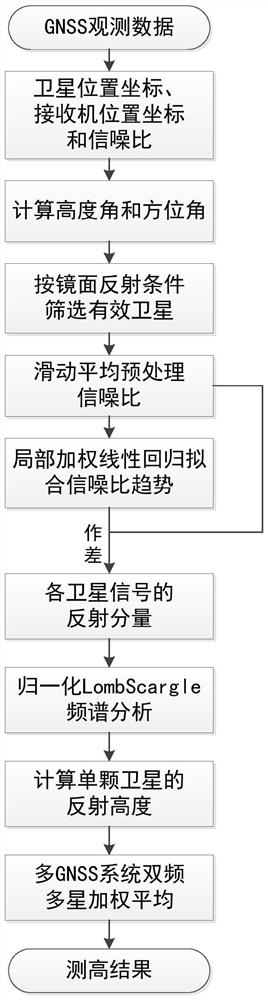
[0059] Now make further description to the specific implementation case of the present invention in conjunction with accompanying drawing.

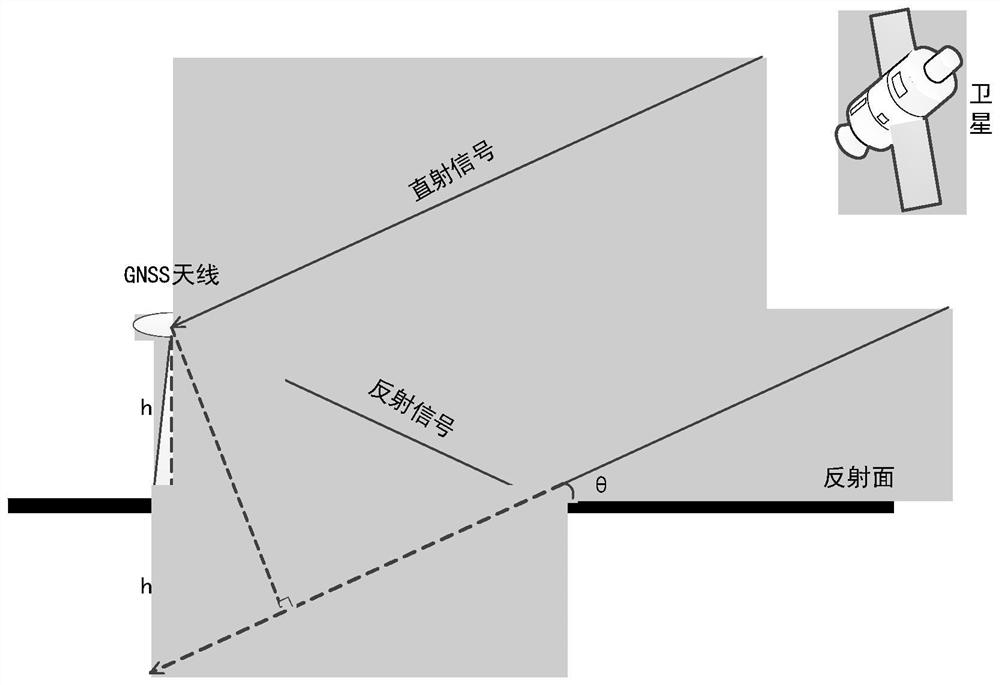
[0060] The present invention utilizes the collected satellite interference signal to calculate the height of the antenna from the reflecting surface, and its principle is explained below:

[0061] figure 2 Geometric model diagram of the multipath effect in the receiving process of the satellite direct signal and reflected signal. Then the power relationship model is as formula (16):

[0062]

[0063] It is assumed that the noise conforms to a Gaussian distribution, and the reflected signal power which is severely weakened during the propagation process is ignored. Then the relationship of signal-to-noise ratio in height measurement satisfies formula (17):

[0064]

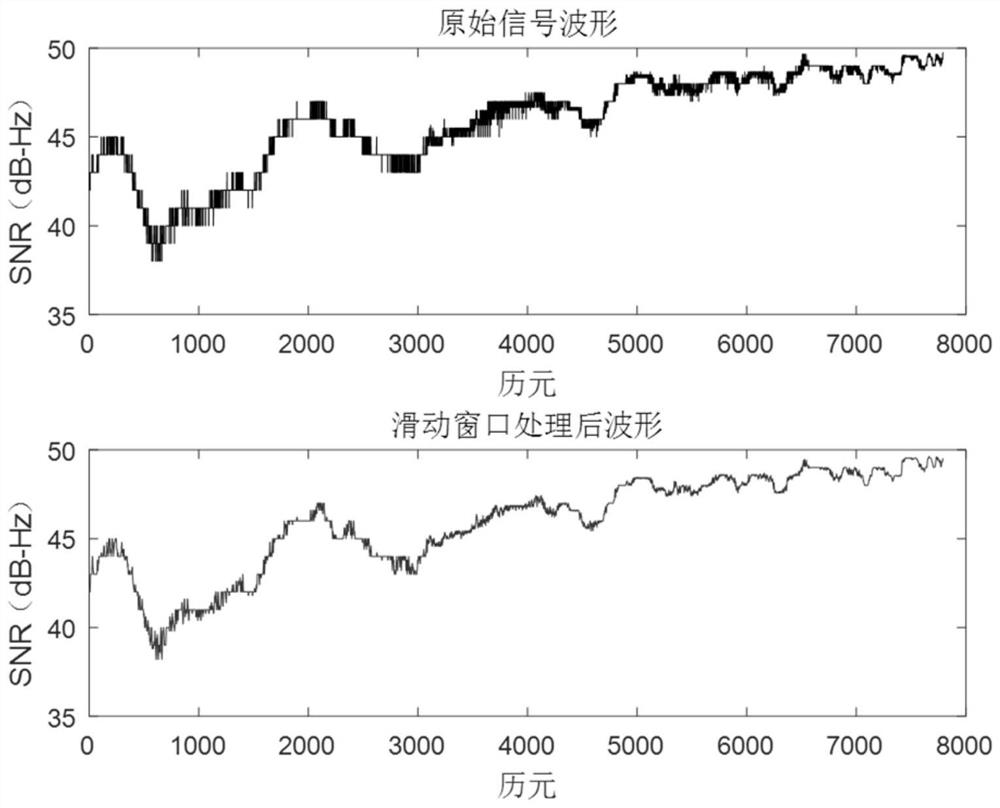
[0065] The multipath signal interferes with the direct signal at the receiving antenna, which will cause oscillation, and the lower the elevation angle, the more coh...


PUM


Abstract

The invention discloses a GNSS-IR height measurement method suitable for a navigation receiver. The method comprises the following steps of: acquiring a satellite in-orbit position coordinate, a signal-to-noise ratio and a user receiver position coordinate by using observation data of a common navigation type GNSS receiver, and calculating a satellite elevation angle and an azimuth angle according to original observed quantity; screening proper satellites according to space-time distribution of an observation scene, and preprocessing a signal-to-noise ratio time sequence by using a moving average method; separating reflection components in a signal-to-noise ratio of each satellite by using a local weighted regression method, performing spectral analysis on the signal-to-noise ratio sequence residual error based on elevation angle reordering, estimating the oscillation frequency of the signal-to-noise ratio of a reflection signal, and calculating the reflection height corresponding to a single satellite according to the oscillation frequency; and optimizing a measurement result of the reflection height through weighting. According to the GNSS-IR height measurement method, the application range is expanded, data resources of the navigation type receiver are fully utilized, the under-fitting problem of a traditional low-order polynomial method can be effectively solved, and the measurement precision and stability are improved.

Description

technical field [0001] The present invention relates to the technical field of navigation positioning and interferometric reflection remote sensing, and mainly relates to the application and optimization of GNSS-IR (Global Navigation Satellite System-Interferometric Reflection, Global Navigation Satellite System Interferometric Reflection Measurement), specifically, a system suitable for navigation receiving Machine-based GNSS-IR altimetry method. Background technique [0002] GNSS interferometric reflectometry is a technology that uses the interference of direct and reflected signals of the Global Navigation Satellite System (GNSS) to obtain the physical parameters of the reflective surface. As a new type of passive non-cooperative remote sensing technology, GNSS-IR has well inherited the advantages of GNSS all-weather, all-weather, no source, wide coverage, high temporal and spatial resolution, and can use the received GNSS reflection signals to realize Feature extraction...

Claims


Application Information

Patent Timeline
Patent Type & Authority Applications(China)
IPC IPC(8): G01S19/42G01C5/00
CPCG01S19/42G01C5/00
Inventor 李方州尚俊娜施浒立
Owner HANGZHOU DIANZI UNIV
Why Eureka
Try Eureka