Ultra-wideband wide-beam embedded end-on-fire skin antenna

A wide-beam, embedded technology, applied in antennas, antenna components, antenna supports/mounting devices, etc., can solve problems such as narrow frequency band, antenna influence, radiation beam influence, etc.

Pending Publication Date: 2021-12-17
CHINA ELECTRONIC TECH GRP CORP NO 38 RES INST
View PDF5 Cites 0 Cited by
  • Summary
  • Abstract
  • Description
  • Claims
  • Application Information

AI Technical Summary

Problems solved by technology

[0003] Traditional missile-borne and airborne skin antennas mostly adopt the form of placing the antenna on the side of the radome. There are big problems in terms of integration and the influence of the radome on the antenna. For side-firing antennas that radiate perpendicular to the radome For example, the microstrip patch antenna unit has a small impact, but it has a great impact on the end-fired antenna. The outstanding problem is the impact on the radiation beam
And traditional missile-borne and airborne skin antennas have a narrow frequency band, which means a lower signal transmission rate and a single function

Method used


Image

  • Ultra-wideband wide-beam embedded end-on-fire skin antenna
  • Ultra-wideband wide-beam embedded end-on-fire skin antenna
  • Ultra-wideband wide-beam embedded end-on-fire skin antenna

Examples


Embodiment Construction

[0016] The above and other technical features and advantages of the present invention will be described in more detail below in conjunction with the accompanying drawings.

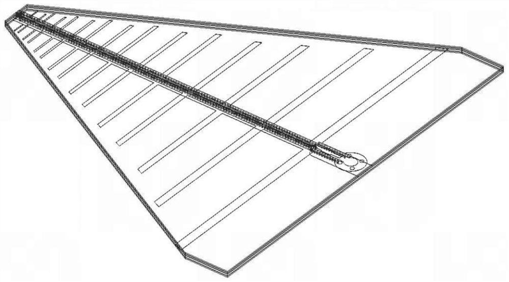
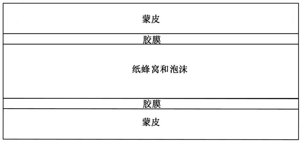
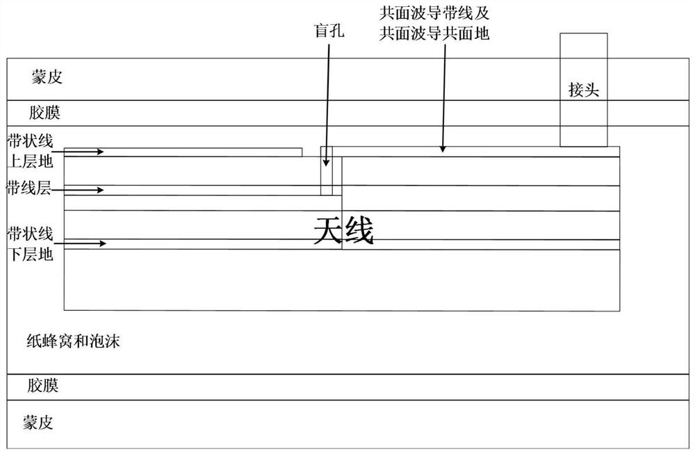
[0017] Such as Figure 1 to Figure 3 as shown, figure 1 is a schematic diagram of the antenna unit; figure 2 is a structural schematic diagram of the radome; image 3 It is a structural schematic diagram of the ultra-wide bandwidth beam embedded skin antenna; Figure 4 is the simulated standing wave diagram of the ultra-wide bandwidth beam embedded skin antenna.

[0018] The ultra-wide bandwidth beam embedded skin antenna of the present invention includes an antenna unit, a skin, a film, a paper honeycomb and a foam, the antenna unit is set in a sheet shape, the foam is set in a sheet shape and the foam and the The shape of the end face of the antenna unit is matched, and the two foams are arranged on both ends of the antenna unit. A placement cavity is arranged in the paper honeycomb, and the antenna...


PUM

PropertyMeasurementUnit
thicknessaaaaaaaaaa

Abstract

The invention discloses an ultra-wideband wide-beam embedded end-on-fire skin antenna. The radiation direction of the ultra-wideband wide-beam embedded end-fire skin antenna is perpendicular to the normal direction of a skin, the ultra-wideband wide-beam embedded end-fire skin antenna comprises an antenna unit, the skin, an adhesive film, a paper honeycomb and foams, the antenna unit is arranged to be in a sheet shape, the foam is arranged to be in a sheet shape, and the shape of the foams is matched with the shape of the end face of the antenna unit; and the two foams are arranged on the two end faces of the antenna unit in an attached mode, a containing cavity is formed in the paper honeycomb, the antenna unit and the foams are arranged in the containing cavity, and the skin is fixedly connected with the end faces of the paper honeycomb through the adhesive film. The ultra-wideband antenna can be embedded into an antenna housing with limited thickness and is subjected to end-fire radiation, and compared with traditional missile-borne and airborne conformal antennas, the antenna has the characteristics of high integration and low profile, and also has the advantages of wide beam coverage range and ultra-wideband.

Description

technical field [0001] The invention relates to the technical field of antennas, in particular to an ultra-wide bandwidth beam embedded end-fire skin antenna. Background technique [0002] Accompanied by the ever-increasing requirements in the military field and positioning systems, ultra-wideband has become more and more attractive, and related design technologies for transmitters and receivers have also appeared one after another shortly thereafter, which has promoted its development. Around 1970, the concept of ultra-wideband technology in practical use was gradually established, mainly in the field of radar and communication. Subsequently, the term "ultra-wideband" was officially proposed by the US Department of Defense in 1989. Later, with the continuous progress of precision manufacturing and processing technology for industrial equipment, from 1990 to the end of the 20th century, this technology entered a period of prosperity and development, and commercial systems al...

Claims


Application Information

Patent Timeline
Patent Type & Authority Applications(China)
IPC IPC(8): H01Q1/42H01Q1/36H01Q5/25H01Q5/50H01Q1/22H01Q1/28
CPCH01Q1/422H01Q1/36H01Q5/25H01Q5/50H01Q1/22H01Q1/285H01Q1/28
Inventor 王一杰刘颂阳陶蕾汪凌霄汪旭宏周继薛伟锋张小林金谋平
Owner CHINA ELECTRONIC TECH GRP CORP NO 38 RES INST
Why Eureka
Try Eureka