Ultra-wideband antenna and equipment

An ultra-wideband antenna and equipment technology, applied in the direction of antenna, antenna grounding device, antenna grounding switch structure connection, etc., can solve the problems of loop antenna frequency band standing wave difference, difficult to widen the working frequency band, etc., achieve small size, expand the working frequency Wide, simple effect

Pending Publication Date: 2021-12-17
ZTE CORP
View PDF0 Cites 1 Cited by
  • Summary
  • Abstract
  • Description
  • Claims
  • Application Information

AI Technical Summary

Problems solved by technology

[0003] The main purpose of the embodiment of the present invention is to propose an ultra-wideband antenna and equipment, aiming to solve the problem of the standing wave difference in some frequency bands of the loop antenna and the difficulty of widening the working frequency band

Method used


Image

  • Ultra-wideband antenna and equipment
  • Ultra-wideband antenna and equipment
  • Ultra-wideband antenna and equipment

Examples


Embodiment 1

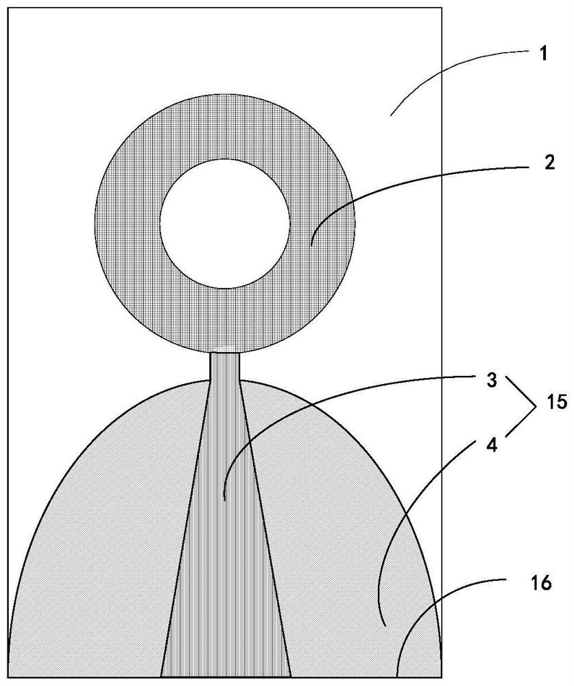
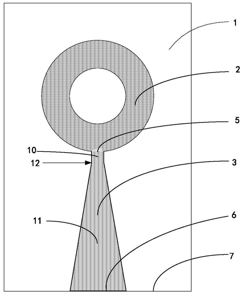
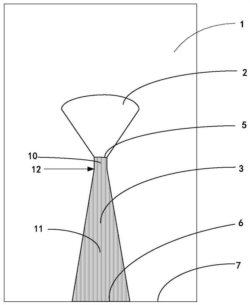
[0039] This embodiment provides an ultra-wideband antenna, including a dielectric substrate, a main radiation unit, and a feed unit, and the feed unit includes a microstrip line feed unit and a ground plate; the dielectric substrate includes a front surface and a back surface opposite to the front surface; the front surface A main radiation unit and a microstrip line feed unit are provided, and the microstrip line feed unit is electrically connected to the main radiation unit; a ground plate is provided on the back; at least a part of the feed unit is from a preset position to the microstrip line feed unit The end or the tail end of the ground plane expansion set.

[0040] See Figure 1-Figure 3 , this embodiment provides an ultra-wideband antenna, the ultra-wideband antenna includes: a dielectric substrate 1, a main radiation unit 2 and a feed unit 15, a microstrip line feed unit 3 and a ground plate 4; wherein:

[0041] The dielectric substrate 1 includes a front surface an...

Embodiment 2

[0082] The implementation of the technical solution in Embodiment 1 will be described in further detail below with a specific application example:

[0083] see Figure 18 , Figure 18 It is a perspective view of another ultra-wideband antenna on the front of a dielectric substrate. The ultra-wideband antenna includes:

[0084] Dielectric substrate 1, the dielectric constant of the dielectric substrate is 4.4, and its dimensions are: length L=1000mil, width W=800mil, and plate thickness 60mil.

[0085] The main radiation unit 2, the ring structure corresponding to the main radiation unit 2 is printed on the top surface of the dielectric substrate 1, the size of the ring is r1=250mil, and r2=120mil.

[0086] The first feeding part 10, the first end of the first feeding part 10 is connected to the main radiation unit 2, the first connection end is connected to the second feeding part 11, and its dimensions are: length Lm2=40mil, Wm2=28mil.

[0087] The second connection end of...

Embodiment 3

[0093] An embodiment of the present invention also provides a device, which includes the ultra-wideband antenna described in any one of the foregoing embodiments.

[0094] In some embodiments, the device includes any one of the following: a mobile phone, a router, a wearable device, a positioning device, and an ultra-wideband communication device.

[0095] In some embodiments, the device may be used for purposes including but not limited to positioning.

[0096] It should be noted that it is worth noting that, in order not to repeat the description, all examples in Embodiments 1 and 2 are not fully described in this embodiment. It should be clear that all examples in Embodiments 1 and 2 are applicable to this embodiment. Example.

[0097] By setting the shape of the ground plate in the ultra-wideband antenna in the device to an exponentially changing structure, the standing wave ratio in the antenna band can be improved and the working frequency band of the antenna can be exp...


PUM

PropertyMeasurementUnit
lengthaaaaaaaaaa
widthaaaaaaaaaa

Abstract

According to an ultra-wideband antenna and equipment provided by the embodiment of the invention, a main radiation unit (2) and a microstrip line feed unit (3) of the ultra-wideband antenna are arranged on the front surface of a dielectric substrate (1), and the microstrip line feed unit (3) is electrically connected with the main radiation unit (2). The grounding plate (4) is arranged on the back surface, opposite to the front surface, of the dielectric substrate (1); and at least one part of the feed unit (15) is expanded from a preset position to the tail end (6) of the microstrip line feed unit (3) or the tail end (16) of the grounding plate (4). The embodiment of the invention further provides equipment, the ultra-wideband antenna can improve the standing-wave ratio and the directional diagram in an antenna band, and the working bandwidth of the antenna is expanded.

Description

technical field [0001] Embodiments of the present invention relate to the field of wireless communication, and in particular, to an ultra-wideband antenna and equipment. Background technique [0002] In recent years, ultra-wideband technology has gradually begun to be applied, which also puts forward higher requirements for antenna technology. The standing wave of the traditional loop antenna is poor in some frequency bands, so it is difficult to widen the working frequency band. Contents of the invention [0003] The main purpose of the embodiments of the present invention is to provide an ultra-wideband antenna and equipment, aiming at solving the problem of the loop antenna having a standing wave difference in some frequency bands and making it difficult to widen the operating frequency band. [0004] To achieve the above purpose, an embodiment of the present invention provides an ultra-wideband antenna, the ultra-wideband antenna includes: [0005] a dielectric subst...

Claims


Application Information

Patent Timeline
Patent Type & Authority Applications(China)
IPC IPC(8): H01Q5/25H01Q1/36H01Q1/38H01Q1/48H01Q1/50
CPCH01Q5/25H01Q1/36H01Q1/38H01Q1/48H01Q1/50H01Q9/40H01Q1/24
Inventor 杨松茂徐殿平
Owner ZTE CORP
Why Eureka
Try Eureka