Insulating layer structure with flow guide function

An insulating layer and functional technology, applied to ships, bulk cargo, and some cabins in the hull, etc., can solve the problems of blind spots in liquid tank leakage detection, unclear leakage liquid diversion paths, and difficult coverage of diversion layers, etc. Achieve the effect of improving detection efficiency and accuracy, improving strength and service life, and improving thermal insulation performance

Pending Publication Date: 2021-12-21
708TH RES INST OF CSSC
View PDF0 Cites 1 Cited by
  • Summary
  • Abstract
  • Description
  • Claims
  • Application Information

AI Technical Summary

Problems solved by technology

Plate insulation has been widely used in the field of B-type tanks. It is supported on the surface of the liquid tank through point support, and the gap between the innermost layer of the insulating plate and the surface of the tank forms a diversion layer for the circulation of leaking liquid or gas. However, there is a problem that the diversion path is not clear for the leaked liquid; since the spray-on insulation needs to be tightly attached to the surface of the tank, it is difficult for the diversion layer used to contain the leaked liquid or gas to cover all the range of the tank surface. There is a blind spot in leak detection

Method used


Image

  • Insulating layer structure with flow guide function
  • Insulating layer structure with flow guide function
  • Insulating layer structure with flow guide function

Examples


Embodiment Construction

[0023] The sizes, proportions, etc. shown in the drawings in this specification are only schematic and used to match the content described in the specification, and are not used to limit the implementation conditions of the present invention, and do not affect the effects of the present invention. The positional relationships such as "upper", "lower", "inner" and "outer" mentioned in this specification are only for convenience of description, and are not used to limit the scope of implementation of the present invention. Substantial changes in technical content are also regarded as the scope of implementation of the present invention.

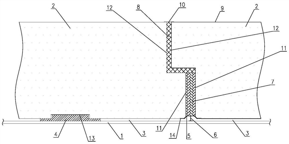
[0024] figure 1 As shown, the present invention provides an insulating layer structure with a conduction function, including a plurality of insulating blocks 2 fixed on the perimeter plate 1 of the liquid tank. The insulating block 2 is fixed by a fixing device 4 and forms a gap with the tank perimeter plate 1 . The innermost part of the gap ...


PUM


Abstract

The invention provides an insulating layer structure with a flow guide function, which comprises a plurality of insulating blocks fixed on a liquid tank peripheral plate, wherein the insulating blocks are fixed by a fixing device and form a gap with the liquid tank peripheral plate, and the innermost side of the gap between two adjacent insulating blocks is covered by a flow guide device, so that a closed circulation layer is formed between the inner surface of the insulating block and the liquid tank peripheral plate, when the liquid tank is damaged, leaked gas or liquid enters a circulation layer, the leaked gas can be detected through a gas detection device, and the leaked liquid can be drained into a special leaked liquid collection device through the flow guide device. Compared with the prior art, the insulating layer structure has the advantages of excellent thermal insulation performance, long service life, high leakage treatment efficiency and convenience in installation.

Description

technical field [0001] The invention relates to an insulating layer structure with a flow-guiding function for an IMO B-type tank, and belongs to the technical field of marine cryogenic liquid tanks. Background technique [0002] Ships used to transport liquefied natural gas, liquefied petroleum gas, and ships that use liquefied natural gas, liquefied petroleum gas or other low-temperature liquid media as fuel must use special tanks for loading low-temperature goods or fuels. An insulating layer is laid on the surface of the tank to maintain the temperature of the liquid in the tank, and at the same time protect the hull structure around the tank from heat. Cryogenic tanks on the market are generally divided into Type A, Type B, Type C and membrane type. According to the design principles of Type B tanks, in addition to the above-mentioned thermal insulation functions, the design of the insulation system also needs to consider that when penetrating cracks occur in the perim...

Claims


Application Information

Patent Timeline
Patent Type & Authority Applications(China)
IPC IPC(8): B63B11/04B63B25/16
CPCB63B11/04B63B25/16
Inventor 郑文青虞赉袁海通高明星郑健王弢
Owner 708TH RES INST OF CSSC
Why Eureka
Try Eureka