Method for tracing, identifying, expanding and increasing yield of water injection dominant channel of water flooding reservoir

A dominant channel and water flooding technology, which is applied in the direction of earthwork drilling, production fluid, wellbore/well components, etc., can solve the problems of long-term measures, high cost, large investment, etc., achieve good results, low transformation cost, Effect of reducing proppant dosage

Pending Publication Date: 2021-12-21
BEIJING GEPETTO OIL TECH
6 Cites 0 Cited by

AI-Extracted Technical Summary

Problems solved by technology

[0004] Aiming at the problems of huge investment, long-term measures and high cost in the tertiary oil recovery technology in the prior art, the present invention provides a method for trace identif...

Method used

S2: use reservoir numerical simulation software to set up dominant channel plugging model, according to relevant parameters such as dominant channel main seepage channel thickness, swept area explained by reservoir geological parameter and tracing interpretation software, use the plugging model of establishment to carry out Reservoir numerical simulation to optimize the plugging area, plugging range, and plugging strength.
S3: adopt profile control agent to block the water flooding dominant channel of the hyperpermeable reservoir section between injection and production wells according to the optimized plugging parameters (blocking area, plugging range, plugging strength), realize water flooding Second tap potential of high-permeability reservoir sections in development reservoirs. The double-sealing and single-carding process is used to inject an economical and environmentally friendly profile control agent into the channeling reservoir section, deeply seal the dominant channel between the injection and production wells, divert the flow of the injected water, and displace the remaining oil in the reservoir, so as to achieve improvement The purpose of recovery in channeling reservoir sections. The specific operation is as follows:
[0046] S31: optimization of profile control agent and injection method design. The oily sludge produced in the development and production of oilfields requires a lot of treatment and seriously pollutes the surrounding environment. It is of great significance to develop and apply oily sludge as a profile control agent for deep profile control and flooding of dominant channels. The designed profile control agent injection method is multi-slug injection, including pre-slug, main slug and post-slug. The front slug is a 1000-2000mg/L high-concentration polymer + cross-linking ...

Abstract

The invention discloses a method for tracing, identifying, expanding and increasing production of a water injection dominant channel of a water flooding reservoir, and belongs to the technical field of oil and gas exploitation. The problems that in the prior art, a tertiary oil recovery technology is huge in investment, long in measure time and high in cost are solved. According to the method, reservoir engineering methods such as tracing monitoring and numerical simulation are applied, and the injected water channeling layer position, the injected water channeling speed, the water injection dominant channel direction, the main seepage channel thickness and the water flooding sweep area in the high water cut period of the water injection development reservoir are accurately positioned. By means of the parameters, reservoir numerical simulation software is used for optimizing the plugging area, the plugging range and the plugging strength, and a water injection dominant channel plugging model is established to serve as the basis of water drive development reservoir profile control construction design. A comprehensive adjustment potential tapping method for profile control of a high-permeability reservoir section of a water injection well of a high-water-cut-period water injection development oil reservoir and hydraulic capacity expansion and augmented injection of a low-permeability reservoir section is adopted, the applicability is higher, the potential tapping measure effect is better, and the method is economical, environmental-friendly and easy and convenient to construct.

Application Domain

Technology Topic

Construction designReservoir engineering +8

Image

  • Method for tracing, identifying, expanding and increasing yield of water injection dominant channel of water flooding reservoir
  • Method for tracing, identifying, expanding and increasing yield of water injection dominant channel of water flooding reservoir
  • Method for tracing, identifying, expanding and increasing yield of water injection dominant channel of water flooding reservoir

Examples

  • Experimental program(1)

Example Embodiment

[0037] In order to make the objects, technical solutions, and advantages of the present application, the technical solutions in the present application embodiment will be described in connext of the present application embodiment, and will be described in connection with the embodiment of the present application embodiment. It is a part of the present application, not all of the embodiments. Components of the present application embodiments described and illustrated in the drawings herein can be arranged and designed in a variety of different configurations. Thus, the following detailed description of the embodiments of the present application provided in the drawings is not intended to limit the scope of the present application claimed, but only the selected embodiments of the present application. Based on the embodiments of the present application, those skilled in the art will belong to the scope of this application under the premise of creative labor.
[0038] In the description of the embodiments of the present application, it is necessary to indicate that the terms "upper", "lower", "left", "right", "vertical", "horizontal", "inside", etc. The orientation or positional relationship is based on the orientation or positional relationship shown in the drawings, or the orientation or positional relationship that is typically placed during the use of the invention, is intended to describe the present application and simplified description, rather than instead of indication or implied. The device or element must have a specific orientation, constructed and operated in a particular orientation, so it is not understood to limit the limitations of the present application. Moreover, the terms "first", "second", "third", etc. are only used to distinguish the description, and cannot be understood as an indication or implied relative importance.
[0039] By below Figure 1-5 The present invention will be described in detail.
[0040] A method of tracing identification and expansion increased production of water-drive reservoirs, including the following steps:
[0041] Step S1, identify the descent flow unit water-drive advantageous channel, numerical simulation of water-drive advantageous channel related parameters, determine the correlation parameters such as the baux flow injection segment, the main penetration channel thickness, the wave, and the area. The specific operation is as follows:
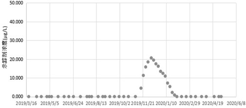
[0042] S11: Select the high-well water well group in which the oil oil efficiency is low in the flow cell is selected for tracer monitoring. A different waterparent tracer is injected into a different waterparent tracer, and the water samples of the oil well are collected every 1-5 days, and the laboratory test is sent to the laboratory test. The concentration of concentrations, the monitoring of the monitoring agent concentration output curve, based on the test results corresponding to the injection well group, determine the injection of the injection of the injection, the direction of the slope, and the speed of promotion (see figure 1.
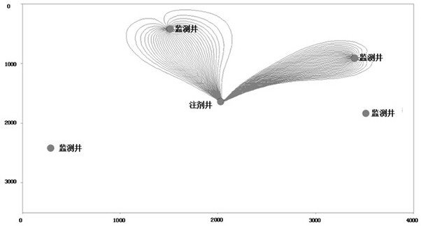
[0043]S12: Application Die Distance Interpretation Software Simulation Water-drive Advantage Channel Related parameters. Collect the reservoir thickness, porosity, penetration, nasale / injection volume, and production data of Nissan oil capacity, etc., and combined with the tracer concentration of the oil production, application well In order to interpret the software, use black oil model to simulate the pressure field, implanted flow line, the main osmosis channel thickness, the wavefront, etc., etc. (see Figure 2 - Figure 4.
[0044] S2: Using reservoir numerical simulation software to establish advantageous channel blocked models, according to the reservoir geological parameters and the intensive interpretation software explained, the main penetration channel thickness, the wavefront of the main penetration channel, and the establishment of the sealing model is used for reservoirs Simulation, optimize the area, blocking range, and sealing strength.
[0045] S3: Adopt anatomical agent according to the optimized blocking parameters (blocking area, sealing range, blocking strength) to block the water-drive advantage of the hydrophilic retentile retentile section of the injection well, to achieve the water-drive development reservoir Secondary digging of high permeability sections. The double-sealing single-card process is injected into the economic environmentally-friendly adjustment agent, and the depth blocking the advantageous channel between the wells, so that the injection of the water flow is turned, and the remaining oil in the reservoir is replaced. The purpose of the recovery rate of the stream reservoir section. The specific operation is as follows:
[0046] S31: Preferred and injecting method for an adjustment agent. Oil-containing sludge treated in oil field development and production, the surrounding environmental pollution is serious, and the development and application of oil-containing mud as an adjustment of the advantageous passage depth anatomy. The design adjustment agent injection method is a multi-segment injection, including the front segment plug, the main segment and the rear segment plug. The front segment is 1000-2000 mg / L high concentration polymer + crosslinking agent segment, which is an object to reduce formation adsorption, and ensure that the main segment is not diluted by the formation water, followed by adjusting the longitudinal permeability of the oil layer, sufficient Play the blockage role of the main segment. The main segment is an oil-containing mud, which acts in adjusting the average of the plane and the in-layer, increasing the area and volume efficiency, and reduces the amount of the polymer. The rear segment is 2000-3000 mg / L high concentration polymer + crosslinking agent segment, the purpose is to increase the blocking ability of the adjustment agent, so that the main segment and subsequent water gradually establish an isolation protection belt to avoid injection The water invaded into the main sector to destroy its stability and flushing of the sludge.
[0047] S32: On-site injection construction of an adjustment agent. On-site preparation of one tuning pump, the maximum injection pressure is 25MPa, injected into the displacement 5-18m 3 / d; 2 liquid tank with stirrer, tolerant 10-15m 3 Each tank import and export and the corresponding control valve; a high-pressure water dragon with a set for connecting the water injection dryer and the liquid tank. On-site construction in the water injection field, the water distribution water is derived from oilfield injection of sewage, which can save construction vehicles, and can solve oilfield sewage problems. From the joint collecting station, the oil tank or the buffered cankage manual hole is discharged from the oil-containing mud to the underground pool, and the tanker is pumped into the well field with a mud pump, discharged into the stirring cell, add a certain amount of suspending agent, additive and solid phase. The particles are mixed well, with anatomical pump 15-18m 3 The displacement of / d is injected into the formation.
[0048] S4: Apply hydraulic expansion modification method to increase the amount of low levy impairment section of water injection wells, and improve the degree of use of low-penetrating reservoirs in the water-drive reservoir. The hydraulic expansion modification method is to produce complex microcracks in the low-diagenesis phase segment than the minimum horizontal main stress (shmin), but does not exceed the rupture pressure. The expansion zone of the penetration is thereby increasing the penetration of the rock mass, increasing the contact area of ​​the reservoir, and achieves the purpose of increasing income. The specific operation is as follows:
[0049] S41: Diagnosis of on-site small cracks in the low seepage segment. The geological mechanical properties of the reservoir are obtained through the on-site reflow assisted DFIT test, such as the three-dimensional main stress, permeability, reservoir pressure, and crack fluid efficiency. Test ground stress and closing pressure of cracks in different directions, perform rock mechanical performance parameters test, and carry out a block stress description. Based on reservoir rock mechanical performance parameters, reservoir physical parameters, quantitative analysis of reservoir stress-strain characteristics, construction pressure, displacement, etc., etc. The degree of expansion affects. This step is usually taken from 8-12 hours to use a liquid without harm to the reservoir.
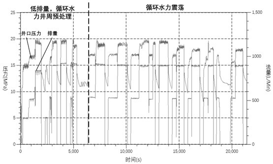
[0050] S42: low displacement, circulating hydraulic well week pretreatment. Application Step S41 Reservoir stress test results, control the injection pressure over the minimum stress of the reservoir, under rupture pressure, use circulating hydraulic injection and reflow, improve geological mechanical parameters such as the ground stress of the well week, and realize The homogenization treatment of the long-range hole section of the well is conducive to the uniform development of the expanded belt (shear crack band) along the longi section. At the same time, the circulating hydraulic load facilitates the uniform use of different direction and the homogeneous artillery eye to achieve a uniform use of the long-term hole segment; the step cycle is generally 12-24 hours, which is required to use a liquid without harm. The resulting construction curve is like Figure 5 Indicated.
[0051] S43: Circulating hydraulic shock. Through the implantation of the wellhead, in the form of injection and reflow, hydraulic shock is generated in the reservoir, stimulates the development of shear cracks and increasing the flow of stratum natural cracks. This step cycle is generally 3-5 hours, which is required to use a liquid without harm. The resulting construction curve is like Figure 5 Indicated.
[0052] The above described embodiments only illustrate the specific embodiments of the present application, which are more specific and detailed, but it is not understood to be limited to the scope of the present application. It should be noted that in terms of one of ordinary skill in the art, several deformations and improvements can be made without departing from the context of the technical solutions of the present application, which belongs to the scope of the present application.

PUM

no PUM

Description & Claims & Application Information

We can also present the details of the Description, Claims and Application information to help users get a comprehensive understanding of the technical details of the patent, such as background art, summary of invention, brief description of drawings, description of embodiments, and other original content. On the other hand, users can also determine the specific scope of protection of the technology through the list of claims; as well as understand the changes in the life cycle of the technology with the presentation of the patent timeline. Login to view more.

Similar technology patents

Methods and devices for analyte sensing in potential spaces

ActiveUS20170281062A1EffectiveFaster insulin deliveryCatheterSensorsSkin temperaturePeritoneal membrane
Owner:THERANOVA LLC

Method for Mediating Dopamine Receptor-Driven Reacidification of Lysosomal pH

InactiveUS20130338145A1EffectiveImprove degradationBiocideTissue cultureLipofuscinDisease
Owner:MITCHELL CLAIRE H +1

Red ginseng extract pellet and preparation method thereof

InactiveCN102462715AEffectiveSmall fluctuations in blood concentrationNervous disorderImmunological disordersPharmaceutical preservativesGINSENG EXTRACT
Owner:JF PHARMALAND TECH DEV

External preparation of essential oil from Bupleurum root

InactiveCN101224227AEffectiveConvenient for clinical selectionAntipyreticAerosol deliverySolventChemistry
Owner:JF PHARMALAND TECH DEV

Novel foundation strengthening method and structure

InactiveCN104005433ASimple technical measuresEffectiveFoundation repairRebarContact position
Owner:上海纺织建筑设计研究院有限公司

Classification and recommendation of technical efficacy words

  • Effective
  • Easy construction

Day care sleeper

Owner:GORDON GEORGE M +1

Balance board

InactiveUS6916276B1Simple designEasy constructionFreely-suspended gymnasticsBalance beamsEngineeringSport training
Owner:ROBINSON STEVEN
Why Eureka
Try Eureka