Intelligent monitoring device for civil engineering structure and use method of intelligent monitoring device

A civil engineering structure and intelligent monitoring technology, applied in the direction of measuring device, gas analyzer structure details, instruments, etc., can solve the problems of insufficient applicability, lack of stable support structure, lack of control and use structure, etc., to achieve easy retractable and Effect of use, good stable support, added applicability

Inactive Publication Date: 2021-12-21
NANYANG INST OF TECH
View PDF2 Cites 0 Cited by
  • Summary
  • Abstract
  • Description
  • Claims
  • Application Information

AI Technical Summary

Problems solved by technology

By setting screws, screw frames, connecting rods and rubber blocks, the monitoring instrument can be reinforced by moving the screw frame, and then the monitoring instrument can be fixed, and then the screw frame drives the screw to move, and then drives the connecting rod to move, so that the rubber block touches the monitor Both sides of the instrument are fixed, so that the monitoring instrument can be fixed on the one hand, and the work efficiency can be improved on the other hand.” However, in this patent, when the device is in use, it lacks a convenient control and use structure, which leads to the inapplicability of the use of the device. Insufficient performance, unable to meet more usage needs;
[0006] 3. The intelligent monitoring device for civil engineering structure and its usage method in the prior art, when in use, most of the air monitoring is mostly hand-held or installed and used, resulting in insufficient protection of the device itself, and the monitoring When working, there is a lack of convenient and stable support structure, and the practicability of the device is insufficient

Method used


Image

  • Intelligent monitoring device for civil engineering structure and use method of intelligent monitoring device
  • Intelligent monitoring device for civil engineering structure and use method of intelligent monitoring device
  • Intelligent monitoring device for civil engineering structure and use method of intelligent monitoring device

Examples


Embodiment 1

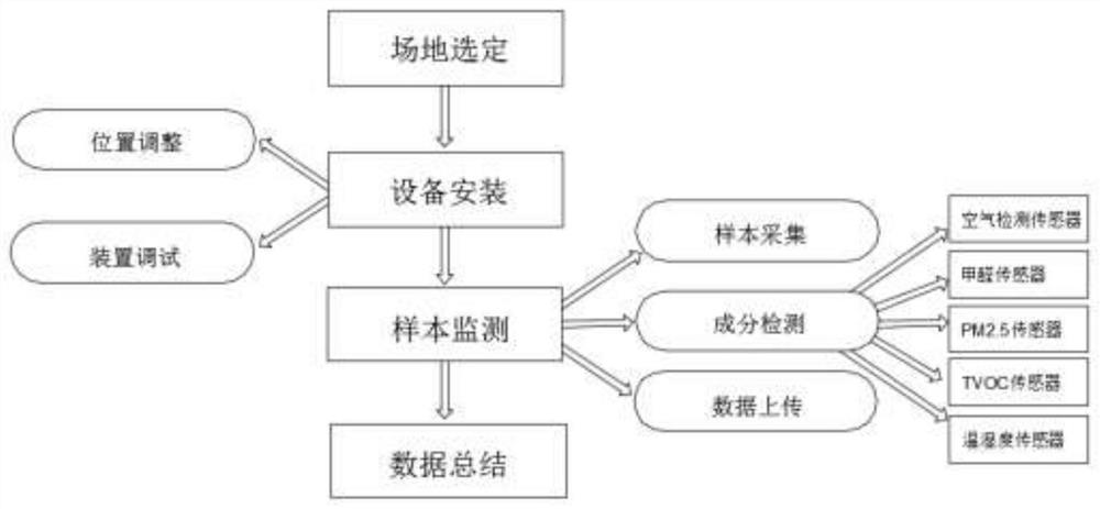
[0034] see figure 2 and image 3, an embodiment provided by the present invention is an intelligent monitoring device for civil engineering structures and a method for using the same, including the following working steps: 1. Site selection; 2. Equipment installation; 3. Air monitoring; 4. Data summary, The selection of the site includes: according to the actual construction environment and the installation site of the construction equipment, the scope of the main work area of ​​the construction personnel and equipment operators is limited, so as to select the appropriate placement location and the placement quantity for the monitoring use, step 3 Air monitoring in the middle includes: sample collection, analysis and comparison, and data upload. After the monitoring equipment is installed, the air samples in the installed environment are collected, and the collected samples are compared with the formaldehyde sensor 16 in the monitoring equipment, so as to compare For the air...

Embodiment 2

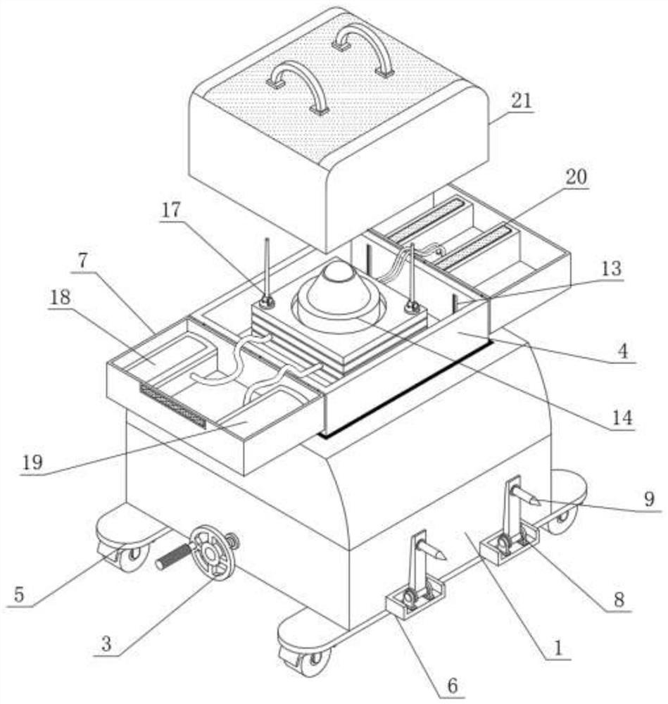
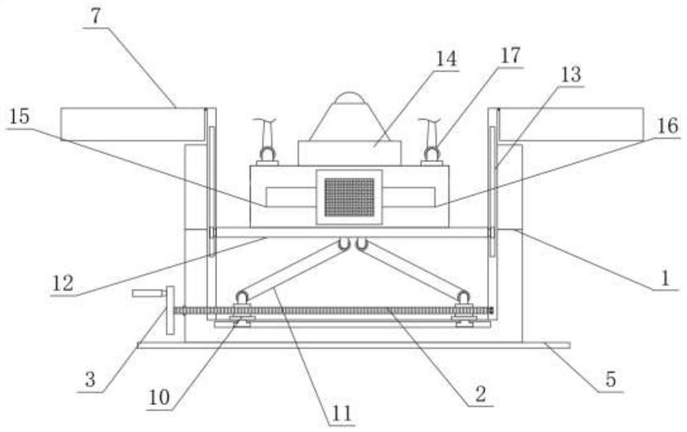
[0037] see figure 1 and figure 2 , an embodiment provided by the present invention is an intelligent monitoring device for civil engineering structures and a method of use thereof, including an adjustment screw 2, a sliding seat 10 and a mounting plate 12, and the equipment installation in step 2 includes position adjustment and device debugging, After formulating the monitoring installation location, complete the installation of monitoring equipment in the corresponding location, and at the same time, make appropriate adjustments to the monitoring according to the actual environmental monitoring requirements, so that the device can achieve the best monitoring status. The position adjustment includes: box body 1, adjusting screw rod 2 and hand crank 3, the front thread of the box body 1 is connected with the adjusting screw rod 2, the front end of the adjusting screw rod 2 is provided with a hand crank handle 3, the inner wall of the box body 1 The limit seat 4 is installed,...

Embodiment 3

[0040] see figure 1 and figure 2 , an embodiment provided by the present invention, an intelligent monitoring device for civil engineering structures and a method of use thereof, comprising a bottom plate 5, a fixing seat 6 and a limit cover 7, a group of bottom plates 5 are installed on the bottom of the box body 1, and the box body Both sides of 1 are equipped with fixed seats 6, the tops of the front and back sides of the limit seat 4 are hinged to limit the cover 7, the top of the fixed seat 6 is fitted with a damping shaft 8, and the outer surface of the damping shaft 8 is connected with Locating the pyramid assembly 9, the bottom of the base plate 5 is provided with universal wheels;

[0041] Through the setting of the bottom plate 5, the limit cover 7, the fixing seat 6, the positioning pyramid assembly 9 and the damping rotating shaft 8, when the device is parked and used, the positioning pyramid assembly 9 is unfolded by rotating the damping rotating shaft 8, and it...


PUM


Abstract

The invention discloses an intelligent monitoring device for a civil engineering structure and a use method of the intelligent monitoring device. The use method comprises the following working steps of 1, site selection; 2, equipment installation; 3, air monitoring; and 4, data summarization, and site selection comprises the step of carrying out range limitation on main working areas of constructors and equipment operators according to the actual construction environment and the installation site of the construction equipment. According to the invention, an air quality detector, an air detection sensor, a formaldehyde sensor, a data transmission module, a PM2.5 sensor, a TVOC sensor and a temperature and humidity sensor are arranged, and the air quality detector, the air detection sensor, the formaldehyde sensor, the PM2.5 sensor, the TVOC sensor, the temperature and humidity sensor and the data transmission module are arranged; the air quality in the construction environment is judged, the components in the collected samples are detected, so that the standard of the air weight in the construction environment is judged, and the detection result is uploaded.

Description

technical field [0001] The invention relates to the technical field of civil engineering monitoring equipment, in particular to an intelligent monitoring device for civil engineering structures and a method for using the same. Background technique [0002] In the construction of civil engineering, due to the repair of the engineering construction, it is necessary to use a large number of large-scale construction equipment. During the use of the equipment, due to environmental factors, some equipment will produce dusty conditions during use, which will affect the construction. The air quality of the site, the air mixed with a lot of dust and the harmful gas emitted by other equipment, makes the air quality of the construction site unfavorable to the health of the construction workers, so real-time monitoring is required for the air quality of the construction environment to Protect the health of construction workers. [0003] The intelligent monitoring devices for civil engi...

Claims


Application Information

Patent Timeline
Patent Type & Authority Applications(China)
IPC IPC(8): G01N33/00
CPCG01N33/0009G01N33/0032
Inventor 张谦李岩杜阳田明娜郭诗惠
Owner NANYANG INST OF TECH
Why Eureka
Try Eureka