Valve welding equipment with lifting, rotating and adjusting integrated function

A technology for lifting and rotating welding equipment, applied in welding equipment, welding equipment, auxiliary welding equipment and other directions, can solve the problems of low welding accuracy, low valve welding efficiency, etc., to increase functionality, convenient adjustment of feeding rotation, The effect of increasing work efficiency

Active Publication Date: 2021-12-24
浙江高中压阀门有限公司
View PDF6 Cites 0 Cited by
  • Summary
  • Abstract
  • Description
  • Claims
  • Application Information

AI Technical Summary

Problems solved by technology

[0003]In the prior art, valve welding equipment usually uses two positioning devices to position the parts to be welded, and make the two parts to be welded close to each other. The welding process is carried out in a hand-held manner. Therefore, during the welding process, it is necessary to continuously load and unload the parts to be welded, and to rotate and position the welding parts to find a suitable position for welding. This not only makes the welding efficiency of the valve to be welded low, Moreover, the welding accuracy is not high, so a valve welding equipment with an integrated function of lifting and rotating adjustment is needed

Method used


Image

  • Valve welding equipment with lifting, rotating and adjusting integrated function
  • Valve welding equipment with lifting, rotating and adjusting integrated function
  • Valve welding equipment with lifting, rotating and adjusting integrated function

Examples


Embodiment Construction

[0021] The following will clearly and completely describe the technical solutions in the embodiments of the present invention with reference to the accompanying drawings in the embodiments of the present invention. Obviously, the described embodiments are only some, not all, embodiments of the present invention. Based on the embodiments of the present invention, all other embodiments obtained by persons of ordinary skill in the art without making creative efforts belong to the protection scope of the present invention.

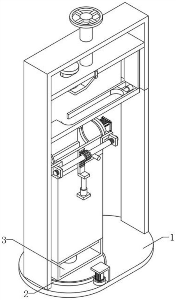
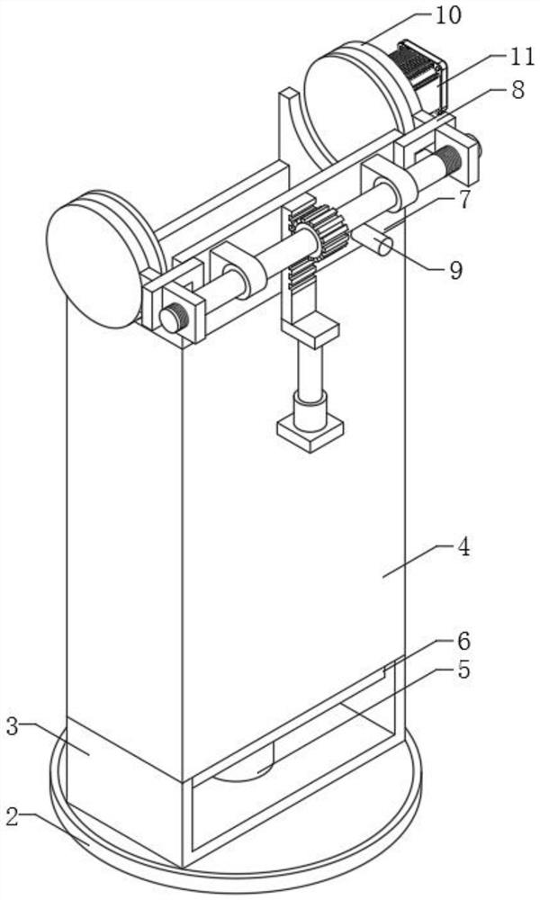
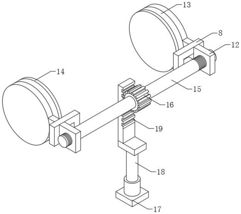
[0022] The present invention provides such Figure 1-5 The valve welding equipment with the integrated function of lifting, rotating and adjusting is shown, which includes a positioning seat 1, a positioning plate 2 is installed on one end of the top of the positioning seat 1, and a switch panel is fixed on one side of the positioning seat 1. The surface is respectively fixed with the first motor switch, the second motor switch, the first electric telescopic r...


PUM


Abstract

The invention discloses valve welding equipment with a lifting, rotating and adjusting integrated function. The valve welding equipment with the lifting, rotating and adjusting integrated function comprises a positioning seat; a positioning disc is rotationally arranged at one end of the top of the positioning seat; a positioning frame is fixedly arranged in the middle of the top of the positioning disc; a first feeding frame is fixedly arranged at the top end of the positioning frame; a first electric telescopic rod is fixedly arranged in the middle of the top of the positioning frame; and a feeding plate is fixedly arranged at the telescopic end of the first electric telescopic rod. According to the invention, to-be-welded valve parts are placed on the first feeding frame and the second feeding frame, the two fixing discs drive the rotating disc and the protective pad on one side to be clamped at the two ends of a first workpiece, the to-be-welded outer ring of a second workpiece is uniformly and stably welded through the welding equipment, so that feeding, rotating and adjusting of the valve welding equipment are more convenient, the working efficiency of valve welding is improved, the welding precision is higher, and the practicability of the valve welding equipment with the lifting, rotating and adjusting integrated function is improved.

Description

technical field [0001] The invention relates to the field of valve welding equipment with the integrated function of lifting and rotating adjustment, in particular to a valve welding equipment with the integrated function of lifting and rotating adjustment. Background technique [0002] Valves are the control components in the fluid delivery system. They have the functions of cut-off, adjustment, flow diversion, reverse flow prevention, pressure stabilization, flow diversion or overflow pressure relief. Valves used in fluid control systems range from the simplest cut-off valve to extremely complex The various valves used in the automatic control system have a wide variety of varieties and specifications. Welding equipment refers to the equipment needed to realize the welding process. Welding equipment includes welding machines, welding process equipment and welding auxiliary appliances. [0003] In the prior art, valve welding equipment usually uses two positioning devices t...

Claims


Application Information

Patent Timeline
Patent Type & Authority Applications(China)
IPC IPC(8): B23K31/02B23K37/00B23K37/04
CPCB23K31/02B23K37/00B23K37/0435
Inventor 朱郁玮戴志伟王栋朱博恩励剑辉吴玉清伍张斌
Owner 浙江高中压阀门有限公司
Why Eureka
Try Eureka