Front-end filtering device of vacuum pump

A front-end filtration and vacuum pump technology, which is applied in the direction of filtration treatment, pump components, variable capacity pump components, etc., can solve the problems of high maintenance cost of vacuum pumps, short cycle of stuck pumps, and blockage of vacuum pumps, etc., so as to improve the effective running time and guarantee Effective operating environment and reduced maintenance costs

Pending Publication Date: 2021-12-24
HENGDIAN GRP DMEGC MAGNETICS CO LTD
View PDF4 Cites 0 Cited by
  • Summary
  • Abstract
  • Description
  • Claims
  • Application Information

AI Technical Summary

Problems solved by technology

With the emergence of the alumina plating process, the conversion efficiency of solar cells has improved, and the demand for alumina equipment is also increasing. However, during the use of alumina equipment, due to the remaining TMA gas after the process is pumped out by the vacuum pump , a large amount of dust will be generated in the vacuum pipeline, and the vacuum pump will be blocked after repeated processes, resulting in serious blockage of the vacuum pump, and the maintenance cost of the vacuum pump is relatively high
Therefore, it is necessary to install a dust catcher at the front end of the vacuum pump. However, the existing dust catcher has an unsatisfactory treatment effect on the exhaust gas. The gas entering the vacuum pump still contains a lot of impurities. The pump stuck cycle is not long, and the production loss is still serious

Method used


Image

  • Front-end filtering device of vacuum pump
  • Front-end filtering device of vacuum pump

Examples


Embodiment Construction

[0038] The present invention will be further described in detail below in conjunction with the accompanying drawings and embodiments. It should be understood that the specific embodiments described here are only used to explain the present invention, but not to limit the present invention. In addition, it should be noted that, for the convenience of description, only some structures related to the present invention are shown in the drawings but not all structures.

[0039] In the description of the present invention, unless otherwise clearly specified and limited, the terms "connected", "connected" and "fixed" should be understood in a broad sense, for example, it can be a fixed connection, a detachable connection, or an integrated ; It can be a mechanical connection or an electrical connection; it can be a direct connection or an indirect connection through an intermediary, and it can be the internal communication of two components or the interaction relationship between two ...


PUM


Abstract

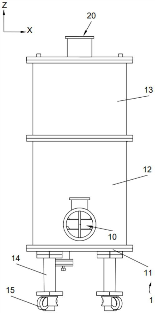
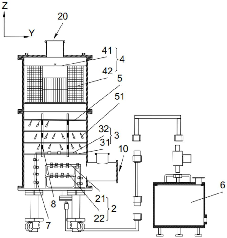
The invention relates to the technical field of photovoltaic coating equipment, and discloses a front-end filtering device of a vacuum pump. The front-end filtering device of the vacuum pump comprises a filtering box, and a heating assembly, a cooling assembly and a filtering assembly which are arranged in the filtering box, wherein a water inlet, an air inlet and an air outlet which are mutually communicated are formed in the filtering box, the water inlet is formed in the bottom of the filtering box and used for being communicated with a water source, the air inlet is formed in the side wall of the filtering box, the air outlet is formed in the upper portion of the filtering box and used for being communicated with a vacuum pump, the heating assembly, the cooling assembly and the filtering assembly are sequentially arranged between the air inlet and the air outlet from bottom to top, the heating assembly can heat water to atomize the water, a cooling liquid is arranged in the cooling assembly, and tail gas can be sequentially subjected to water mist thermal reaction by the heating assembly, condensed by the cooling assembly to remove impurities, filtered by the filtering assembly, subjected to gas-liquid separation and then input into the vacuum pump. The vacuum pump front-end filtering device can guarantee the effective operation environment of the vacuum pump and reduce the maintenance cost of the vacuum pump.

Description

technical field [0001] The invention relates to the technical field of photovoltaic coating equipment, in particular to a filter device at the front end of a vacuum pump. Background technique [0002] Tubular PECVD equipment is one of the main equipment for coating equipment in the photovoltaic industry. With the emergence of the alumina plating process, the conversion efficiency of solar cells has improved, and the demand for alumina equipment is also increasing. However, during the use of alumina equipment, the remaining TMA gas after the process is pumped out by the vacuum pump. , a large amount of dust will be generated in the vacuum pipeline, and the vacuum pump will be blocked after repeated processes, resulting in serious blockage of the vacuum pump, and the maintenance cost of the vacuum pump is relatively high. Therefore, it is necessary to install a dust catcher at the front end of the vacuum pump. However, the existing dust catcher has an unsatisfactory treatment...

Claims


Application Information

Patent Timeline
IPC IPC(8): C02F9/10B01D53/00F04B39/16
CPCC02F9/00B01D53/002F04B39/16C02F1/001C02F1/043C02F1/16C02F1/008
Inventor 孙述任良为王春来金晨淦
Owner HENGDIAN GRP DMEGC MAGNETICS CO LTD
Why Eureka
Try Eureka