
Steel frame-support connecting joint based on thickness design of main connecting plate

A technology for connecting nodes and main connections, which is applied in the direction of architecture and building construction, etc. It can solve the problems of heavy welding workload and complicated fire prevention treatment, and achieve the effect of reducing construction difficulty, welding work difficulty and coverage area

Active Publication Date: 2021-12-24
HANGZHOU TONGMSK DESIGN CO LTD
View PDF6 Cites 0 Cited by
  • Summary
  • Abstract
  • Description
  • Claims
  • Application Information

AI Technical Summary

Problems solved by technology

The welding workload of this node is heavy, and the fire prevention treatment is more complicated

Method used


Image

  • Steel frame-support connecting joint based on thickness design of main connecting plate
  • Steel frame-support connecting joint based on thickness design of main connecting plate
  • Steel frame-support connecting joint based on thickness design of main connecting plate

Examples


Embodiment 1

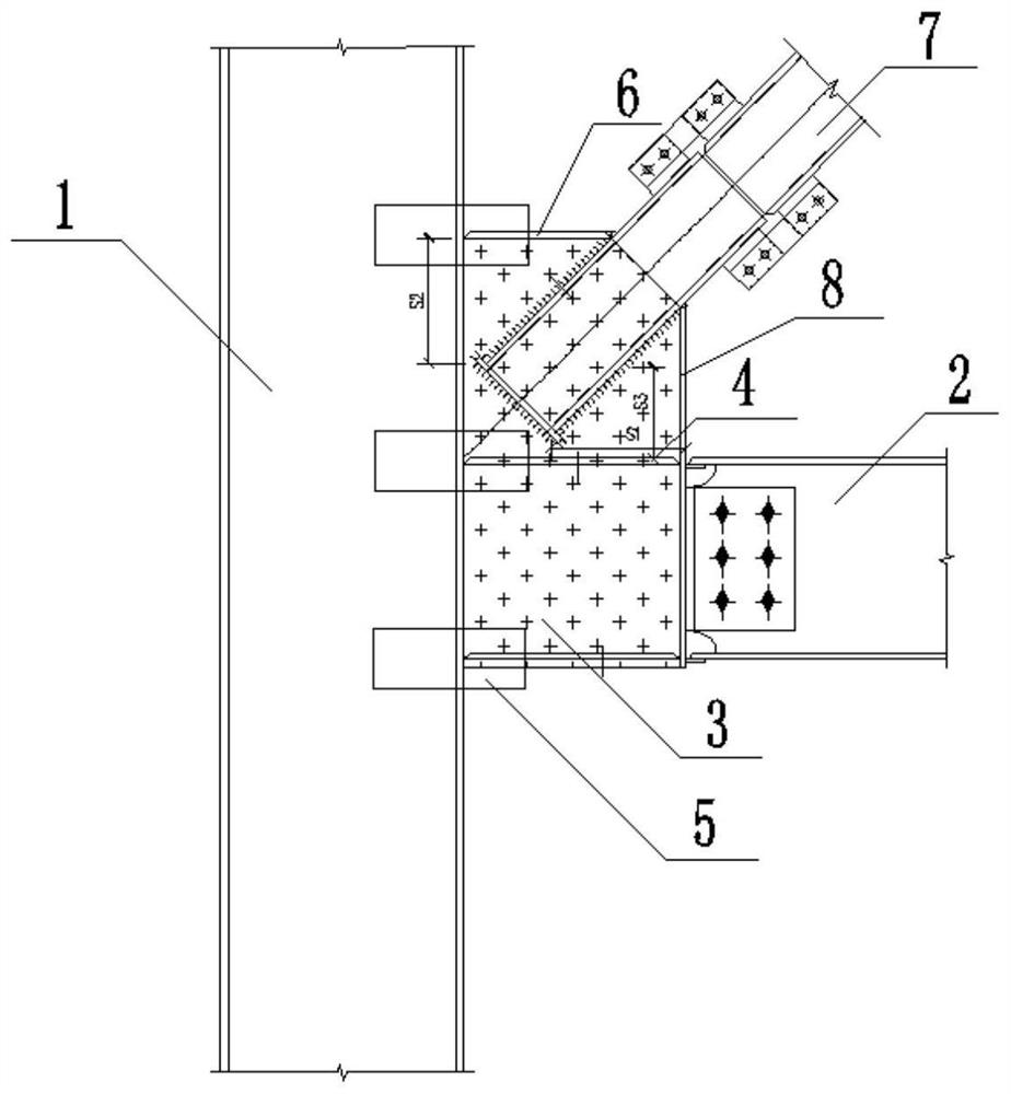
[0048] The joints include wide steel column 1, beam 2, main connecting plate 3, horizontal stiffener 4, pasting plate 5 and support section 7, the connection between wide steel column 1 and beam 2, and the end of beam 2 passes through main connecting plate 3 and wide The outer wall of the steel column 1 is connected; wherein, the horizontal height of the bottom of the beam is aligned with the bottom end of the main connecting plate.

[0049] Such as Figure 1-Figure 5 As shown, the main connecting plate 3 is vertically arranged, one end is welded and fixed to the outer wall of the wide steel column 1, and the other end is welded and fixed to the end of the beam 2, and the web of the main connecting plate 3 and the beam 2 is located on the same vertical plane; Horizontal stiffeners 4 are welded on both sides of the upper and lower ends of the main connecting plate 3 where the upper and lower flanges of the beam 2 are at the same height, that is, on both sides of the main connec...

Embodiment 2

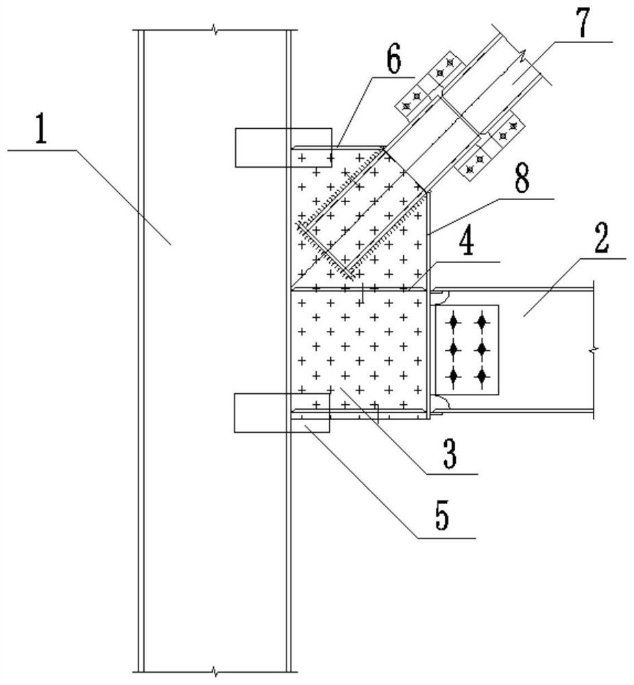
[0058] Such as figure 2 As shown, remove the two sticking plates 5 welded to the horizontal stiffener 4 in the middle of the main connecting plate 3 in Embodiment 1 of the steel frame-supporting connection node of the present invention.

Embodiment 3

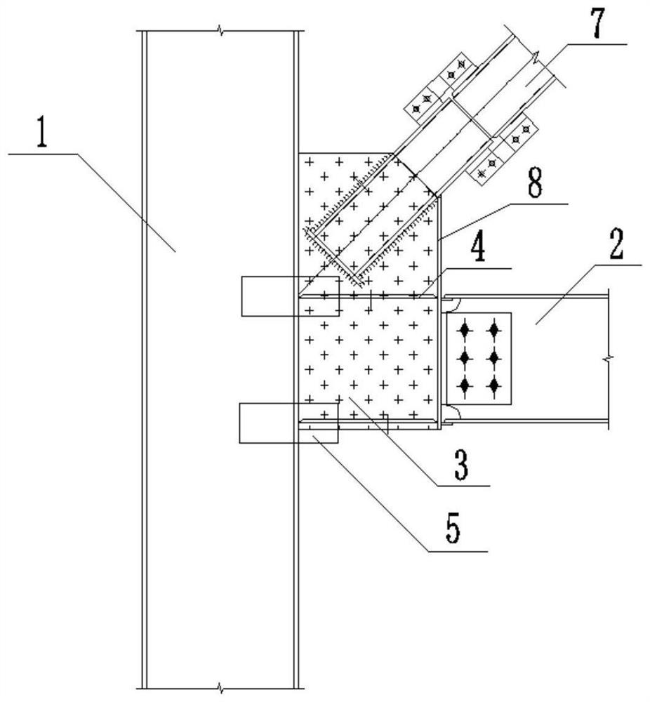
[0060] Such as image 3 As shown, the cover plate 6 welded to the upper section of the main connecting plate 3 and the two subplates 5 welded to the side of the cover plate 6 in Embodiment 1 of the steel frame-support connection node of the present invention are removed.


PUM


Abstract

The invention discloses a steel frame-support connecting joint based on the thickness design of a main connecting plate. An beam end part is connected with the outer wall surface of a wide steel column through the main connecting plate; horizontal stiffening ribs are welded on two side surfaces of the upper end and the lower end of the main connecting plate with the same height of an upper flange and a lower flange of the beam; a flitch plate is arranged at the joint between the main connecting plate and the outer wall surface of the wide steel column; an inclined groove with the inclination angle of 45 degrees is formed in the part, protruding out of the beam, of the upper end of the main connecting plate, the lower end of the supporting section is obliquely inserted into the inclined groove, and the upper end of the supporting section is connected with an external part; and a sealing plate is arranged at the lower end of the supporting section. The steel frame-support connecting joint has enough bearing capacity, ductility and energy dissipation capacity, and the structural safety is reliably guaranteed; and meanwhile, the steel use amount and the welding workload of the joint are effectively reduced, the difficulty and uncontrollability of site construction operation are reduced, and application is wide.

Description

technical field [0001] The invention belongs to a building connection node in the technical field of structural design, and in particular relates to a design method for a support connection node of a steel frame and a calculation method for the plate thickness of a main connection plate. Background technique [0002] Concrete-filled steel pipe columns are formed by pouring concrete into empty steel pipes. Concrete has high compressive strength and steel has high flexural strength. Concrete-filled steel pipe columns can combine the two points in structure to improve the bending resistance of concrete. Strength and deformation capacity, the concrete inside the steel pipe can effectively prevent local buckling and instability of the steel pipe, so the CFST column has excellent mechanical properties, specifically manifested in the characteristics of high bearing capacity, high ductility, and high earthquake resistance. Moreover, the concrete inside the steel tube can absorb heat...

Claims


Application Information

Patent Timeline
Patent Type & Authority Applications(China)
IPC IPC(8): E04B1/24E04B1/58
CPCE04B1/24E04B1/2403E04B1/58E04B2001/2406
Inventor 付波贾树华薛国庆童振华孙浩李梓捷
Owner HANGZHOU TONGMSK DESIGN CO LTD
Learn More