Pump valve assembly and sphygmomanometer using same

A sphygmomanometer and component technology, applied in the direction of cardiac catheterization, etc., can solve problems such as complicated wiring, troublesome production, assembly and after-sales maintenance, and achieve the effects of space integration saving, reducing pipelines, and reducing noise

Pending Publication Date: 2021-12-28
JIANGSU YUYUE MEDICAL EQUIP&SUPPLY CO LTD +3
View PDF0 Cites 0 Cited by
  • Summary
  • Abstract
  • Description
  • Claims
  • Application Information

AI Technical Summary

Problems solved by technology

However, the traditional full-automatic tunnel-type sphygmomanometers inflated with airbags are not designed in a modular manner. There are both wires and trachea in the casing, and the wiring is complicated. It is very troublesome for its production, assembly and after-sales maintenance.

Method used


Image

  • Pump valve assembly and sphygmomanometer using same
  • Pump valve assembly and sphygmomanometer using same

Examples


Embodiment 1

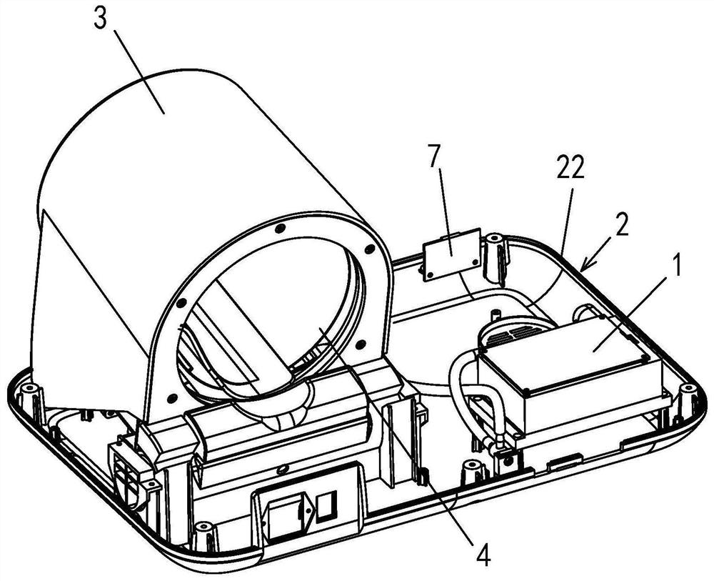
[0029] Embodiment one: see Figure 1~2 Shown:

[0030] A sphygmomanometer, a tunnel-type sphygmomanometer for fully automatic balloon inflation, see figure 1 As shown, it includes a seat body 2, an arm barrel 3 installed on the seat body 2, and an air bag assembly 4 arranged in the arm barrel 3, and also includes a pump valve assembly 1, and the assembly bracket 15 of the pump valve assembly 1 is fixedly installed on on the seat body 2.

[0031] The pedestal 2 is for example made up of the lower base plate 22 of the pedestal and the upper cover of the pedestal, figure 1 The upper cover of the middle base is in the state of being opened and removed. The assembly bracket 15 is fixedly installed on the seat body 2, specifically on the lower bottom plate 22 of the seat body, and is covered by the upper cover of the seat body.

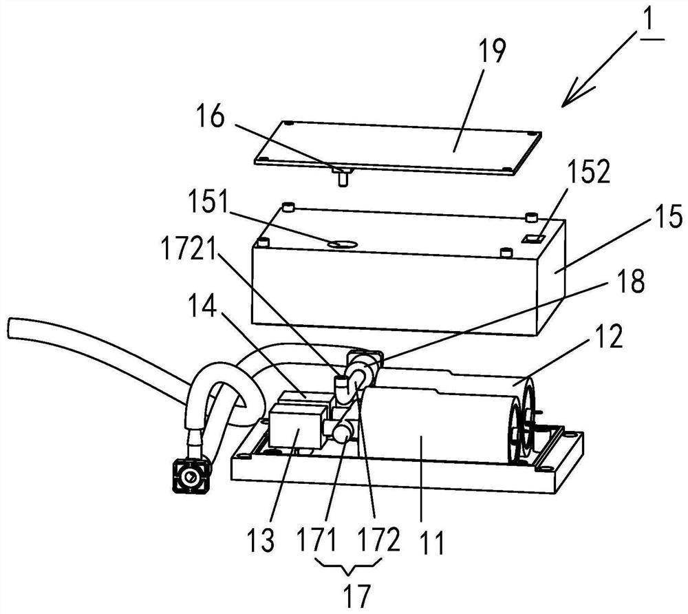
[0032] see figure 2 As shown, the pump valve assembly 1 includes a first air pump 11, a second air pump 12, a first air release valve 13, a second ai...

Embodiment 2

[0040] Embodiment two: see Figure 1~2 Shown:

[0041] A sphygmomanometer pump valve assembly 1, including a first air pump 11, a second air pump 12, a first air release valve 13, a second air release valve 14, a pipeline assembly and an assembly bracket 15, specifically the pump in Embodiment 1 The structure of the valve assembly 1 is the same and will not be repeated here.


PUM


Abstract

The invention discloses a pump valve assembly and a sphygmomanometer using the same. The pump valve assembly comprises a first inflator pump (11), a second inflator pump (12), a first air release valve (13), a second air release valve (14) and a pipeline assembly, and the pipeline assembly is respectively communicated with the first inflator pump (11), the second inflator pump (12), the first air release valve (13) and the second air release valve (14); and the pump valve assembly is characterized by further comprising an assembly support (15), the first inflator pump (11), the second inflator pump (12), the first air release valve (3) and the second air release valve (14) are all arranged on the assembly support (15), the assembly support (15) is provided with a first opening and a second opening (151), and the pipeline assembly is communicated with an air bag (4) and a pressure sensor (16) through the first opening and the second opening (151) in an air flow manner. The pump valve assembly 1 can be produced independently, and subjected to accurate calibration and after-sale maintenance, and production line sub-module independent production is better facilitated.

Description

technical field [0001] The invention relates to medical equipment, in particular to a pump valve assembly and a fully automatic electronic sphygmomanometer using the pump valve assembly. Background technique [0002] Usually, there are two methods of measuring blood pressure: auscultatory and oscillometric. The auscultation method is mainly applied to mercury sphygmomanometers, which requires professional medical personnel to operate, and its use has limitations; while the oscillometric method is mainly applied to electronic sphygmomanometers, which does not require professional medical personnel to operate, and even the elderly can operate by themselves. It is simple and convenient to use, and electronic sphygmomanometers are mostly selected for home use. At present, most electronic sphygmomanometers on the market use the oscillometric method to measure blood pressure. The main method is to first inflate the cuff to block the arterial blood flow, and then detect the gas pr...

Claims


Application Information

Patent Timeline
Patent Type & Authority Applications(China)
IPC IPC(8): A61B5/0235A61B5/0225
CPCA61B5/0235A61B5/0225
Inventor 魏贺张佳陶涛赵帅
Owner JIANGSU YUYUE MEDICAL EQUIP&SUPPLY CO LTD
Why Eureka
Try Eureka